Mitsubishi Lancer Evolution IX. Manual - part 511


  Index      Mitsubishi     Mitsubishi Lancer Evolution IX - service repair manual


Search            


Content   ..  509  510  511  512   ..


Mitsubishi Lancer Evolution IX. Manual - part 511


TROUBLESHOOTING

ANTI-SKID BRAKING SYSTEM (ABS)

35B-75

Code No.81: Steering Wheel Sensor (ST-1) System


Code No.82: Steering Wheel Sensor (ST-2) System


Code No.83: Steering Wheel Sensor (ST-N) System

OPERATION

The steering wheel sensor monitors the steering 
angle and sends the ST-1, ST-2 and ST-N signals. 
The ABS-ECU calculates the steering angle by read-
ing the signals from the steering wheel sensor.

DIAGNOSIS CODE SET CONDITIONS

Diagnosis code No.81 (ST-1), No.82 (ST-2) and 
No.83 (ST-N) are set if there is a fault in the steering 
wheel sensor, an open circuit or short circuit in the 
signal lines, or the internal circuit in the hydraulic unit 
and ABS-ECU is defective.
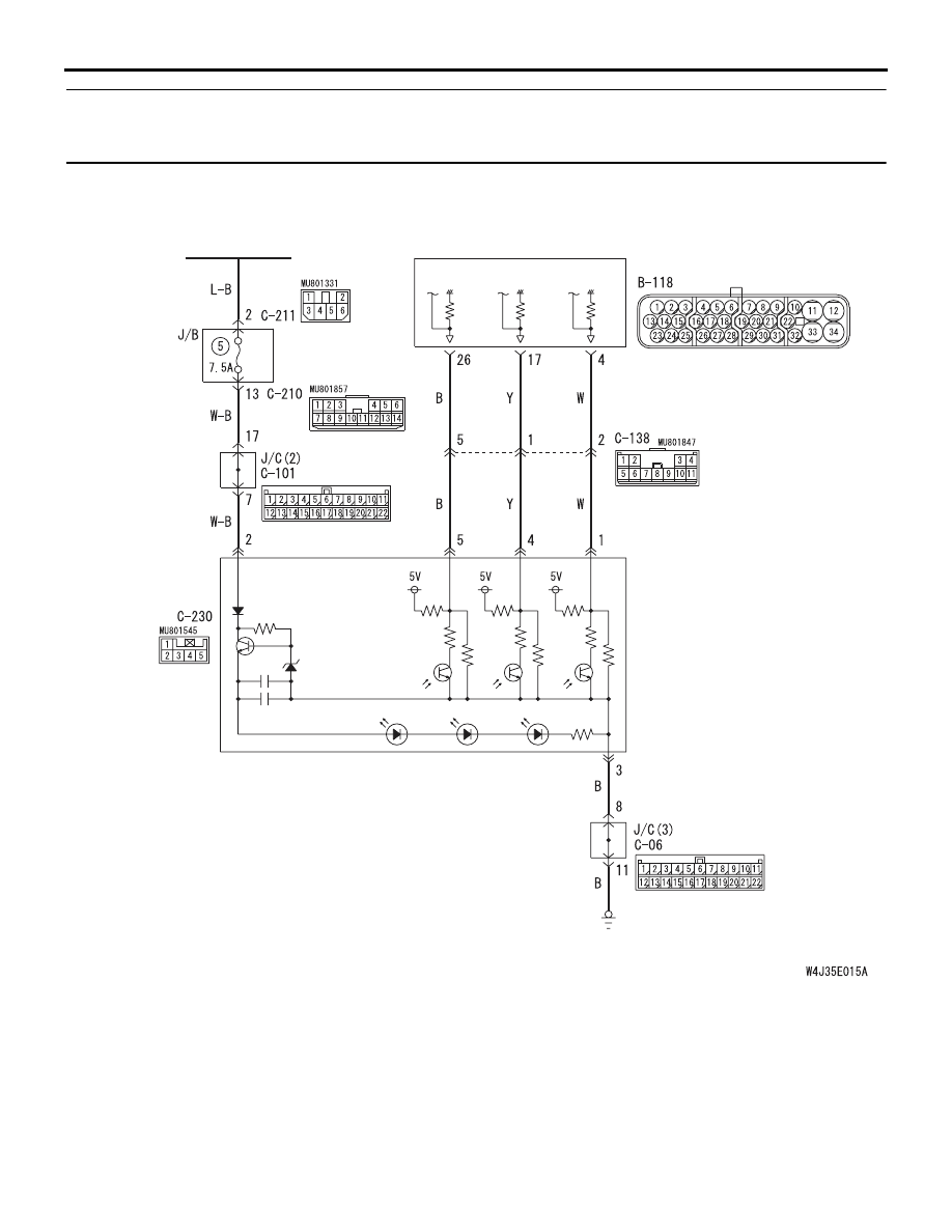
IGNITION
SWITCH (IG2)

STEERING
WHEEL
SENSOR

ABS-ECU

Wire colour code
B : Black     LG : Light green     G : Green     L : Blue
W : White     Y : Yellow     SB : Sky blue     BR : Brown
O : Orange     GR : Gray     R : Red     P : Pink     V : Violet

Steering Wheel Sensor Circuit

ST-1

ST-2

ST-N

TROUBLESHOOTING

ANTI-SKID BRAKING SYSTEM (ABS)

35B-76

PROBABLE CAUSES

The most likely causes for these diagnosis codes to 
set are:

• Malfunction of the steering wheel sensor

• Damaged wiring harness and connector

• Malfunction of the brake modulator hydraulic unit 

(integrated with ABS-ECU)

DIAGNOSIS

STEP 1. M.U.T.-II/III data list.

CAUTION

To prevent damage to M.U.T.-II/III, always turn the 
ignition switch to the "LOOK" (OFF) position 
before connecting or disconnecting M.U.T.-II/III.

(1) Connect M.U.T.-II/III as shown in the illustration.

(2) Start the engine.
(3) Set M.U.T.-II/III to data reading mode for following 

items.

• Item No.74: Steering wheel (ST−N)

• Item No.75: Steering wheel (ST−1)

• Item No.76: Steering wheel (ST−2)

OK:

Q: Is the steering wheel sensor input normal?

YES : 

This malfunction is intermittent. Refer to 

GROUP 00, How to Use 
Troubleshooting/Inspection Service Points 

− 

How to Cope With Intermittent Malfunction 

P.00-5

NO : 

Go to Step 2.

AC311157

Steering shaft

AB

MB991502

<Using the M.U.T.-II>

AC311153

AB

MB991911

16-PIN

MB991827

MB991824 

<Using the M.U.T.-III>

Item 
No.

Check item

Checking 
requirement

Display

74

Steering 
wheel sensor 
(ST-N)

Steering: Neutral 
position and 
position near by 
± 360°

ON

Steering: Except 
for above

OFF

75

Steering 
wheel sensor 
(ST-1)

Steering: Turn 
laterally slowly.

Display 
ON and 
OFF 
alternately

76

Steering 
wheel sensor 
(ST-2)

TROUBLESHOOTING

ANTI-SKID BRAKING SYSTEM (ABS)

35B-77

STEP 2. Check the power supply circuit. Voltage 
measurement at steering wheel sensor 
connector C-230.

(1) Disconnect connector C-230, and check at the 

harness side.

(2) Turn the ignition switch to the "ON" position.
(3) Measure the voltage between terminal 2 and 

earth.

OK: System voltage

Q: Is the check result normal?

YES : 

Go to Step 3.

NO : 

Go to Step 4.

STEP 3. Check the earth circuit. Resistance 
measurement at steering wheel sensor 
connector C-230.

(1) Disconnect connector C-230, and check at the 

harness side.

(2) Measure the resistance between terminal 3 and 

earth.

OK: 2 ohms or less

Q: Is the resistance 2 ohms or less?

YES : 

Go to Step 8.

NO : 

Go to Step 6.

AC311195AB

Connector: C-230

Connector C-230
(Harness side)

5 4

1
2

3

AC311195AC

Connector: C-230

Connector C-230
(Harness side)

5 4

1
2

3

TROUBLESHOOTING

ANTI-SKID BRAKING SYSTEM (ABS)

35B-78

STEP 4. Check the following connectors.

Steering wheel sensor connector C-230

Junction block connectors C-210, C-211

Joint connector C-101
Check the connectors for loose, corroded or dam-
aged terminals, or terminals pushed back in the con-
nector.

Q: Are the connectors and terminals in good 

condition?
YES : 

Go to Step 5.

NO : 

Repair it and then go to Step 11.

STEP 5. Check the following harness wire.

The wire between steering wheel sensor connector 
C-230 (terminal 2) and junction block connector 
C-211 (terminal 2)

Q: Is the harness wire damaged?

YES : 

Repair or replace it and then go to Step 11.

NO : 

Go to Step 11.

AC311196AB

Connector: C-230

Harness side

5 4

1
2

3

AC311164

Connectors: C-210, C-211

C-210

C-211

AB

Junction block
(Front view)

Connector C-210
(Harness side)

4

6 5

3

2

1

10

1

6

14

5

12

13

4

11

7

2

3

8

9

Connector C-211
(Harness side)

AC311161AE

Connector: C-101

C-101 (L)

2

1

3

13

12

14

21

10

5

4

6

16

15

17

7 8 9

19

18

20

11

22

AC311196AB

Connector: C-230

Harness side

5 4

1
2

3

AC311165

Connector: C-211 

AB

Junction block
(Front view)

Harness side

4

6 5

3

2

1


Content   ..  509  510  511  512   ..