Mitsubishi Lancer Evolution IX. Manual - part 484


  Index      Mitsubishi     Mitsubishi Lancer Evolution IX - service repair manual


Search            


Content   ..  482  483  484  485   ..


Mitsubishi Lancer Evolution IX. Manual - part 484


INJECTOR

MULTIPORT FUEL INJECTION (MPI)

13A-411

INJECTOR

REMOVAL AND INSTALLATION

M1131007100854

Pre-removal Operation
• Fuel Discharge Prevention (Refer to 

P.13A-398

).

• Strut Tower Bar Removal (Refer to GROUP 42, Strut 

Tower Bar 

P.42-9

).

• Air Hose E, Air By-pass Hose, Air Pipe C Removal (Refer 

to GROUP 15, Intercooler 

P.15-6

).

Post-installation Operation
• Air Hose E, Air By-pass Hose, Air Pipe C Installation 

(Refer to GROUP 15, Intercooler 

P.15-6

).

• Strut Tower Bar Installation (Refer to GROUP 42, Strut 

Tower Bar 

P.42-9

).

• Fuel Leakage Check
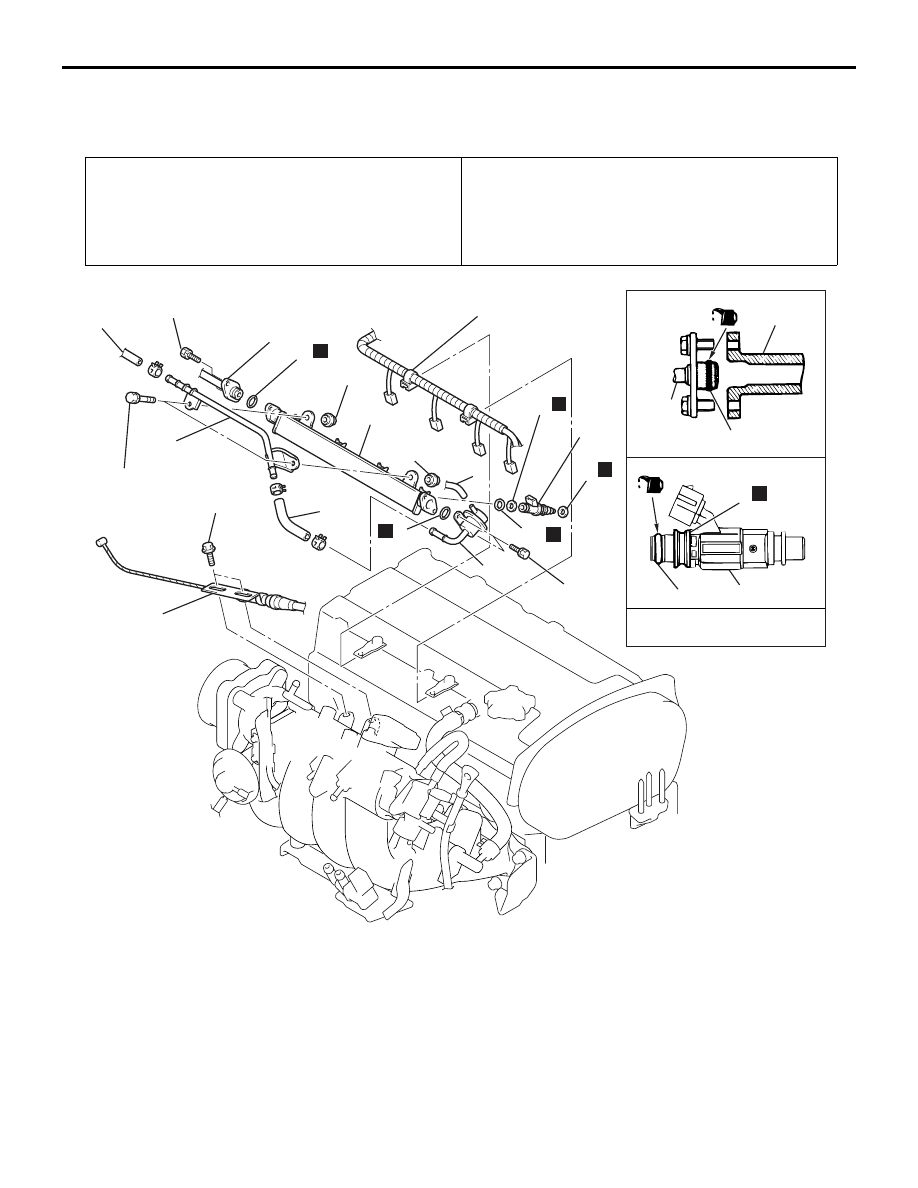
AC210060AD

8.9 ± 1.9 N·m

14

Engine oil

15

N

O-ring

O-ring

1

N

10

11

12

12

13

15

N

N

N

N

5.0 ± 1.0 N·m

5.0 ± 1.0 N·m

11 ± 1 N·m

,

3 7

3

9

5

5

4

10

8

7

13

2

6

Removal steps 

1.

Accelerator cable assembly 
connection (Throttle body side)

2.

Control wiring harness connection

>>

A

<< 3.

Fuel high-pressure hose 
connection

4.

O-ring

5.

Fuel return hoses connection

6.

Vacuum hose connection

>>

A

<< 7.

Fuel pressure regulator

8.

O-ring

9.

Fuel return pipe

<<

A

>>

10. Delivery pipe
11. Insulators
12. Insulators

<<

A

>> >>

A

<< 13 Injectors

14. O-ring
15. Grommets

Removal steps (Continued)

INJECTOR

MULTIPORT FUEL INJECTION (MPI)

13A-412

REMOVAL SERVICE POINT
<<A>> DELIVERY PIPE/INJECTORS 
REMOVAL

CAUTION

Do not drop the injector.
Remove the delivery pipe with the injectors attached 
to it.

INSTALLATION SERVICE POINT
>>A<< INJECTORS/FUEL PRESSURE 
REGULATOR/FUEL HIGH-PRESSURE 
HOSE INSTALLATION

CAUTION

Do not let the engine oil get into the delivery pipe 
will be damaged.
1. Apply a drop of new engine oil to the O-ring.

2. Turn the injector to the right and left to install to 

the delivery pipe. Repeat for fuel pressure 
regulator and fuel high-pressure hose. Be careful 
not to damage the O-ring. After installing, check 
that the item turns smoothly.

3. If it does not turn smoothly, the O-ring may be 

pinched, remove the item, re-install it into the 
delivery pipe and check again.

4. Tighten the fuel pressure regulator and fuel 

high-pressure hose to the specified torque.

Tightening torque:

8.9 

± 1.9 Nm <Fuel pressure regulator>

5.0 

± 1.0 Nm <Fuel high-pressure hose>

THROTTLE BODY ASSEMBLY

MULTIPORT FUEL INJECTION (MPI)

13A-413

THROTTLE BODY ASSEMBLY

REMOVAL AND INSTALLATION

M1131007700759

Pre-removal Operation
• Under Cover Removal (Refer to GROUP 51, Front 

Bumper 

P.51-2

).

• Engine Coolant Draining (Refer to GROUP 14, On-vehicle 

Service 

− Engine Coolant Replacemen

P.14-15

).

• Strut Tower Bar Removal (Refer to GROUP 42, Strut 

Tower Bar 

P.42-9

).

• Air Hose E, Air By-pass Hose, Air Pipe C Removal (Refer 

to GROUP 15, Intercooler 

P.15-6

).

Post-installation Operation
• Air Hose E, Air By-pass Hose, Air Pipe C Installation 

(Refer to GROUP 15, Intercooler 

P.15-6

).

• Strut Tower Bar Installation Refer to GROUP 42, Strut 

Tower Bar 

P.42-9

).

• Engine Coolant Refilling (Refer to GROUP 14, On-vehicle 

Service 

− Engine Coolant Replacement 

P.14-15

).

• Under Cover Installation (Refer to GROUP 51, Front 

Bumper 

P.51-2

).

• Accelerator Cable Adjustment (Refer to GROUP 17, 

On-vehicle Service 

− Accelerator Cable Check and 

Adjustment 

P.17-2

).

AC310860

AB

N

19 ± 3 N·m    

5.0 ± 1.0 N·m    

1

2

3

4

5

6

7

5

Removal steps 

1.

Accelerator cable connection

2.

Throttle position sensor connector

3.

Idle speed control servo connector

4.

Vacuum hoses connection

5.

Water hoses connection

6.

Throttle body

>>

A

<< 7.

Throttle body gasket

Removal steps (Continued)

THROTTLE BODY ASSEMBLY

MULTIPORT FUEL INJECTION (MPI)

13A-414

INSTALLATION SERVICE POINT
>>A<<THROTTLE BODY GASKET 
INSTALLATION

CAUTION

Poor idling etc. may result if the throttle body 
gasket is installed incorrectly.

Install the throttle body gasket as shown in the illus-
tration.

AC200313AB

Towards front 
of vehicle

Up


Content   ..  482  483  484  485   ..