Mitsubishi Lancer Evolution IX. Manual - part 356


  Index      Mitsubishi     Mitsubishi Lancer Evolution IX - service repair manual


Search            


Content   ..  354  355  356  357   ..


Mitsubishi Lancer Evolution IX. Manual - part 356


ENGINE CONTROL

ENGINE AND EMISSION CONTROL

17-3

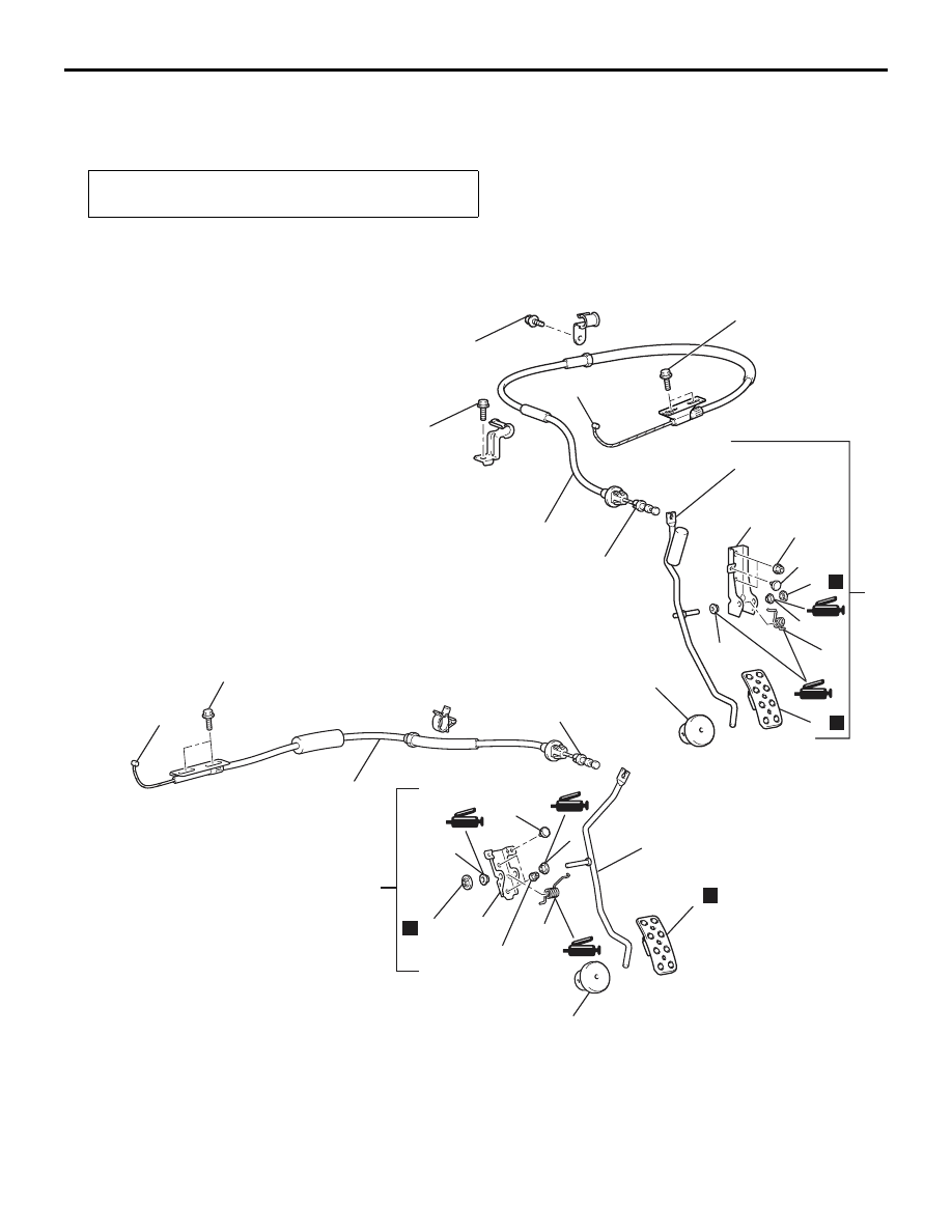
ACCELERATOR CABLE AND PEDAL

REMOVAL AND INSTALLATION

M1171001200608

Post-installation Operation
Adjusting the Accelerator Cable (Refer to 

P.17-2

).

AC505002

1

10

4

6

7

8

6

2

11

5

9

12 ± 2 N·m

5.0 ± 1.0 N·m    

11 ± 1 N·m

N

5.0 ± 1.0 N·m

AB

10

11

12

3

N

5

1

12

3

N

8

7

6

12 ± 2 N·m

9

4

N

6

5.0 ± 1.0 N·m    

2

<R.H. drive vehicles>

<L.H. drive vehicles>

Accelerator pedal removal steps 

>>

B

<< 1. Inner cable connection (Accelerator 

pedal side)

2. Accelerator pedal assembly

>>

A

<< 3. Accelerator pedal pad

4. Push-on spring nut
5. Accelerator pedal arm assembly

6. Bushing
7. Spring
8. Stopper
9. Accelerator pedal bracket

Accelerator pedal removal steps 

Accelerator cable removal steps 

>>

B

<< 1. Inner cable connection (Accelerator 

pedal side)

10. Inner cable connection (Throttle lever 

side)

11. Accelerator cable assembly

Accelerator pedal stopper removal 
 

12. Accelerator pedal stopper

EMISSION CONTROL <MPI>

ENGINE AND EMISSION CONTROL

17-4

INSTALLATION SERVICE POINTS
>>A<< ACCELERATOR PEDAL PAD 
INSTALLATION

Warm the peg of the accelerator pedal pad with a 
dryer before installing the pad.
NOTE: If it is difficult to fit, apply soapy water to the 
peg lightly.

>>B<< INNER CABLE INSTALLATION

AC210048

Plastic bushing

Accelerator
cable

Accelerator
pedal arm

Rubber dumper

AB

Securely fit the plastic bushing on the inner cable of 
the accelerator cable to the accelerator pedal arm as 
shown.

EMISSION CONTROL <MPI>

GENERAL INFORMATION

M1173000100541

The emission control system consists of the following 
subsystems:

• Crankcase emission control system

• Evaporative emission control system

Items

Name

Specification

Crankcase emission control 
system

Positive crankcase ventilation 
(PCV) valve

Variable flow type (Purpose: HC 
reduction)

Evaporative emission control 
system

Canister
Purge control solenoid valve
Check valve

Equipped
Duty cycle type solenoid valve
Equipped
(Purpose: HC reduction)

Exhaust emission control system

Air-fuel ratio control device - MPI 
system

Oxygen sensor feedback type 
(Purpose: CO, HC, NOx reduction)

Exhaust gas recirculation system

• EGR valve

• EGR control solenoid valve

Equipped
Single type
Duty cycle type solenoid valve 

(Purpose: NOx reduction)

Catalytic converter

Monolith type (Purpose: CO, HC, 
NOx reduction)

Exhaust emission control system

EMISSION CONTROL <MPI>

ENGINE AND EMISSION CONTROL

17-5

EMISSION CONTROL DEVICE 
REFERENCE TABLE

M1173006600180

Related parts

Crankcase 
emission 
control 
system

Evaporative 
emission 
control 
system

Air/fuel ratio 
control 
system

Catalytic 
converter

Exhaust gas 
recirculation 
system

PCV valve

×

Purge control solenoid valve

×

Check valve

×

MPI system component

×

×

Catalytic converter

×

EGR valve

×

EGR control solenoid valve

×

SERVICE SPECIFICATIONS

M1173000300448

Items

Standard value

Purge control solenoid valve coil resistance (at 20

°C) Ω

30 

− 34

EGR control solenoid valve coil resistance (at 20

°C) Ω

29 

− 35

SPECIAL TOOL

M1173000600256

Tool

Number

Name

Use

MD998770

Oxygen sensor wrench

Removal and installation of 
oxygen sensor

EMISSION CONTROL <MPI>

ENGINE AND EMISSION CONTROL

17-6

VACUUM HOSE

VACUUM HOSE PIPING DIAGRAM

M1173000900796

AK501844 AB

From 
fuel tank

Canister

Check valve

Fuel pressure 
control solenoid 
valve

Purge control 
solenoid valve

Air inlet

Oxygen sensor (front)

Catalytic converter

Catalytic converter

Oxygen sensor (rear)

Injector

EGR control 
solenoid valve

From 
fuel pump

Fuel pressure 
regulator

To fuel 
tank

EGR 
valve

PCV 
valve


Content   ..  354  355  356  357   ..