Mitsubishi Lancer Evolution IX. Manual - part 292
AK204166AF
28
29
30
31
32
33
34
35
35
48
36
36
37
38
39
40
41
42
43
44
51
45
46
47
49
50
52
53
54
55
56
57
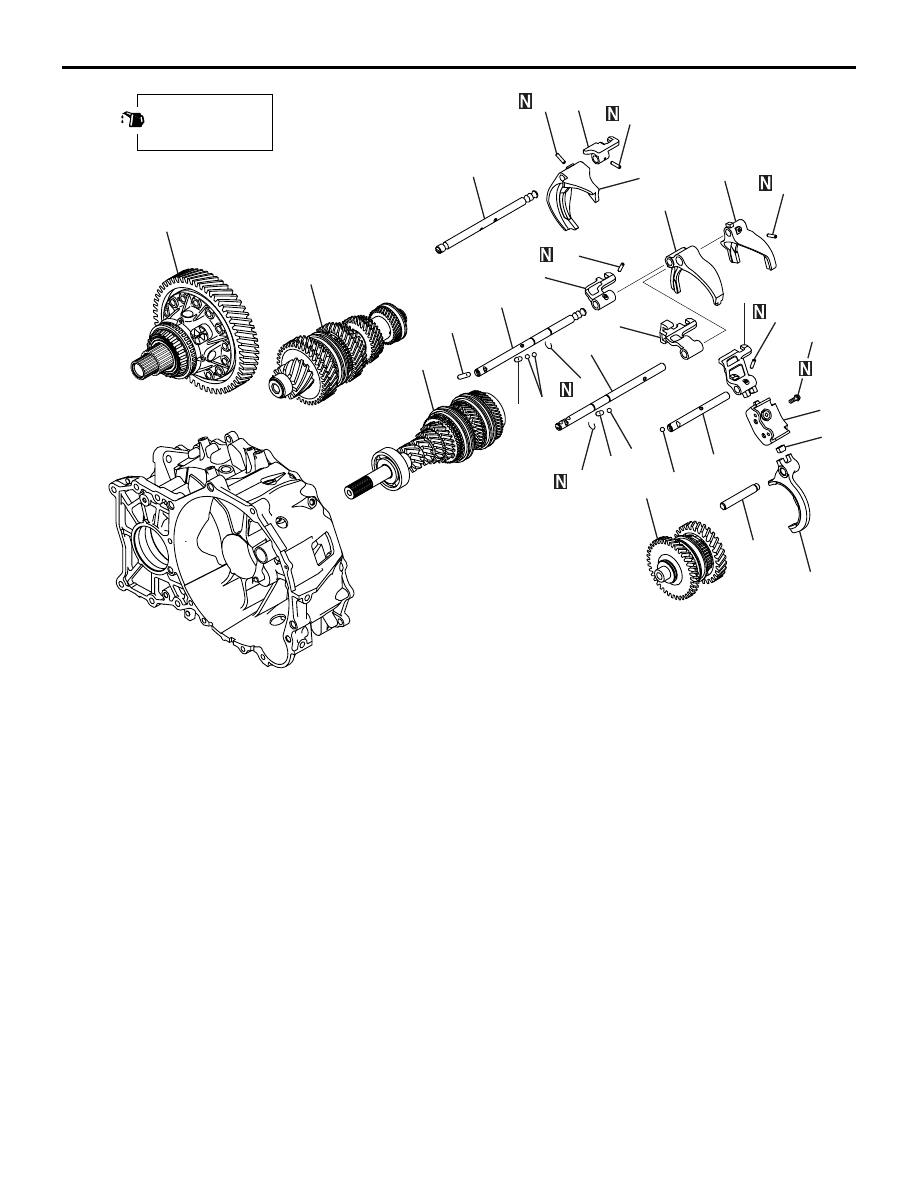
14 ± 1 N·m
Apply gear oil to
all moving parts
before installation.
Disassembly steps
28. Reverse lever assembly
29. Shifter cap
30. Reverse fork rod
31. Reverse shift fork
32. Retaining pin
33. Reverse bracket
34. Reverse bracket fork rod
35. Interlock ball
36. Retaining pin
37. 1st-2nd bracket
38. 1st-2nd fork rod
39. 1st-2nd shift fork
40. Retaining pin
41. C-ring
42. 3rd-4th fork rod
43. Interlock pin
44. 3rd-4th bracket
45. Retaining pin
46. C-ring
47. 5th-6th fork rod
48. Interlock pin
49. 5th-6th shift fork
50. 3rd-4th shift fork
51. 5th-6th bracket
52. Interlock ball
53. Shift check sleeve
54. Main shaft assembly
55. Input shaft assembly
56. Reverse idler gear assembly
57. Center differential
TRANSMISSION
MANUAL TRANSMISSION OVERHAUL
22B-13
Reassembly steps
57. Center differential
>>A<<
56. Reverse idler gear assembly
>>A<<
55. Input shaft assembly
>>A<<
54. Main shaft assembly
38. 1st-2nd fork rod
37. 1st-2nd bracket
36. Retaining pin
>>B<<
39. 1st-2nd shift fork
>>C<<
53. Shift check sleeve
>>D<<
42. 3rd-4th fork rod
43. Interlock pin
>>D<<
44. 3rd-4th bracket
>>D<<
50. 3rd-4th shift fork
Disassembly steps (Continued)