Mitsubishi Lancer Evolution IX. Manual - part 249


  Index      Mitsubishi     Mitsubishi Lancer Evolution IX - service repair manual


Search            


Content   ..  247  248  249  250   ..


Mitsubishi Lancer Evolution IX. Manual - part 249


SYMPTOM PROCEDURES

SMART WIRING SYSTEM (SWS) USING SWS MONITOR

54C-255

Step 2. SWS monitor data list.
Check the input signals below, which are related to 
the door-ajar warning lamp.

<Selected item> ETACS ECU

• Driver's door: open 

OK: Normal condition is displayed.

Q: Is the check result normal?

YES : 

Go to Step 3.

NO : 

Refer to Inspection Procedure L-3 "The door 
switch (front: LH) signal is not received <LH 
drive vehicles>

P.54C-263

 ," or refer to 

Inspection Procedure L-3 "The door switch 
(front: RH) signal is not received <RH drive 
vehicles>

P.54C-265

 ."

Step 3. Pulse check
Check the input signals below, which are related to 
the door-ajar warning lamp.

OK: The M.U.T.-II/III sounds or the voltmeter 
needle fluctuates.

Q: Is the check result normal?

YES : 

Go to Step 4.

NO : 

Refer to Inspection Procedure L-11 "All the 
door switch signals are not received <LH 
drive vehicles>

P.54C-289

 ," or refer to 

Inspection Procedure L-11 "All the door 
switch signals are not received <RH drive 
vehicles>

P.54C-292

 ."

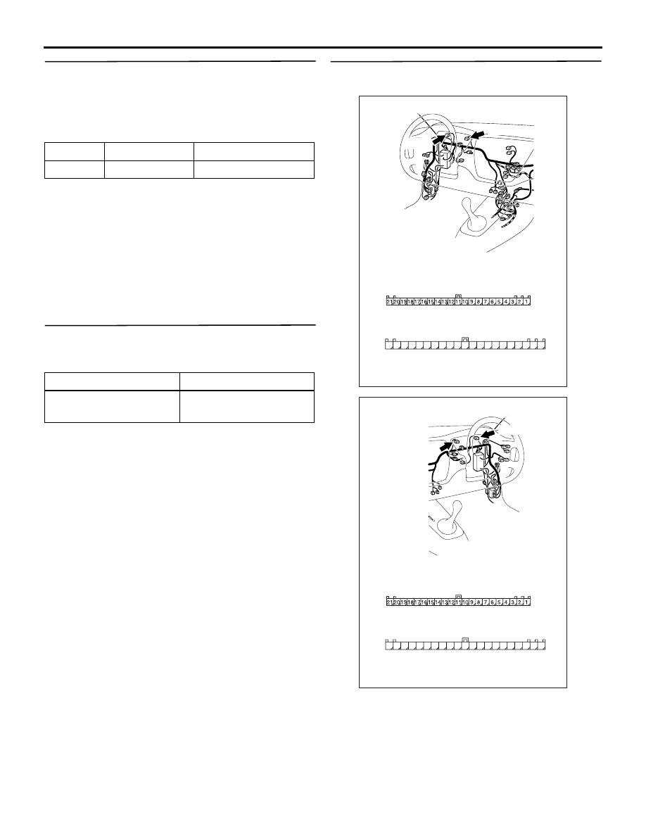
Step 4. Connector check: C-01 and C-02 
combination meter connector

Q: Is the check result normal?

YES : 

Go to Step 5.

NO : 

Repair the defective connector.

Item No.

Item name

Normal condition

Item 32

DR DOOR SW ON

System switch

Check condition

All of the door switches

A door is opened when 
all the doors are closed

AC310447

Connectors: C-01, C-02

AE

<LHD>

C-01
Harness side

C-02 
Harness side

31

32

33

34

35

36

37

38

39

40

41

42

43

44

45

46

47

48

49

50

51

C-01

C-02(L)

AC310457

Connectors: C-01, C-02

AB

<RHD>

C-01
Harness side

C-02 
Harness side

31

32

33

34

35

36

37

38

39

40

41

42

43

44

45

46

47

48

49

50

51

C-01

C-02(L)

SYMPTOM PROCEDURES

SMART WIRING SYSTEM (SWS) USING SWS MONITOR

54C-256

Step 5. Check the door-ajar warning lamp bulb.
Check the door-ajar warning lamp bulb.

Q: Is the check result normal?

YES : 

Go to Step 6.

NO : 

Replace the door-ajar warning lamp bulb.

Step 6. Connector check: C-228 ETACS-ECU 
connector

Q: Is the check result normal?

YES : 

Go to Step 7.

NO : 

Repair the defective connector.

AC310450

Connector: C-228

AH

Junction block 
(rear view)

Harness side

<LHD>

51

52

53

54

55

56

57

58

59

58 5756 55 54 53 52 51 60

74 7372

71 70 69

AC310461

Harness side

Junction block (rear view)

Connector: C-228

AG

<RHD>

51

52

53

54

55

56

57

58

59

58 5756 55 54 53 52 51 60

74 7372

71 70 69

SYMPTOM PROCEDURES

SMART WIRING SYSTEM (SWS) USING SWS MONITOR

54C-257

Step 7. Check the wiring harness from C-228 
ETACS-ECU connector terminal Nos.53 and 71 to 
C-02 combination meter connector terminal 
No.34 and C-01 combination meter connector 
terminal No.8.

• Check the input or output lines for open circuit.

Q: Is the check result normal?

YES : 

Go to Step 8.

NO : 

Repair the wiring harness.

Step 8. Retest the system.
Replace the ETACS-ECU, and then check that the 
door-ajar warning lamp illuminates/extinguishes nor-
mally.
(1) Replace the ETACS-ECU.
(2) Check that the door-ajar warning lamp 

illuminates/extinguishes normally.

Q: Is the check result normal?

YES : 

The trouble can be an intermittent 

malfunction (Refer to GROUP 00 

− How to 

Cope with Intermittent Malfunction 

P.00-5

).

NO : 

Replace the combination meter.

AC310450

Connector: C-228

AH

Junction block 
(rear view)

Harness side

<LHD>

51

52

53

54

55

56

57

58

59

58 5756 55 54 53 52 51 60

74 7372

71 70 69

AC310461

Harness side

Junction block (rear view)

Connector: C-228

AG

<RHD>

51

52

53

54

55

56

57

58

59

58 5756 55 54 53 52 51 60

74 7372

71 70 69

AC310447

Connectors: C-01, C-02

AE

<LHD>

C-01
Harness side

C-02 
Harness side

31

32

33

34

35

36

37

38

39

40

41

42

43

44

45

46

47

48

49

50

51

C-01

C-02(L)

AC310457

Connectors: C-01, C-02

AB

<RHD>

C-01
Harness side

C-02 
Harness side

31

32

33

34

35

36

37

38

39

40

41

42

43

44

45

46

47

48

49

50

51

C-01

C-02(L)

INPUT SIGNAL PROCEDURES

SMART WIRING SYSTEM (SWS) USING SWS MONITOR

54C-258

INPUT SIGNAL PROCEDURES

INSPECTION PROCEDURE L-1: The ignition switch (ACC) signal is not received.

CAUTION

Whenever the ECU is replaced, ensure that the 
input signal circuit is normal.

COMMENTS ON TROUBLE SYMPTOM

Input signal from the ignition switch (ACC) is used to 
operate the functions below. If the signal is abnormal, 
these functions will not work normally.

• Windshield wiper and washer

• Rear wiper and washer

• Interior lamp automatic shutdown function

POSSIBLE CAUSES

• Malfunction of the ETACS-ECU

• Damaged harness wires and connectors

Wire colour code
B : Black     LG : Light green     G : Green     L : Blue     W : White     Y : Yellow     SB : Sky blue
BR : Brown     O : Orange     GR : Gray     R : Red     P : Pink     V : Violet   

ETACS-ECU

IGNITION 
SWITCH (ACC)

J/B SIDE

Ignition Switch (ACC) Input Circuit


Content   ..  247  248  249  250   ..