Mitsubishi Lancer Evolution IX. Manual - part 106
GENERAL DATA AND SPECIFICATIONS
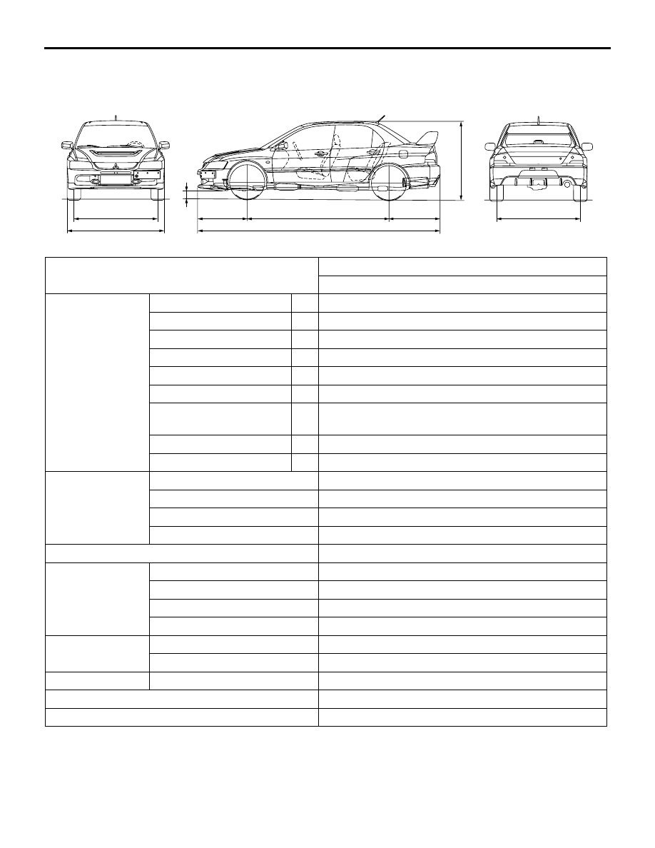
GENERAL
00-17
GENERAL DATA AND SPECIFICATIONS
M1001000901045
AC505135
1
2
7
3
4
6
5
8
9
AB
Items
CT9A
SJGFZL6/R6
Vehicle
dimensions mm
Front track
1
1,515
Overall width
2
1,770
Front overhang
3
930
Wheel base
4
2,625
Rear overhang
5
935
Overall length
6
4,490
Ground clearance
(unladen)
7
140
Overall height (unladen)
8
1,450
Rear track
9
1,515
Vehicle weight kg Kerb weight
1,465
Max. gross vehicle weight
1,885
Max. axle weight rating-front
1,015
Max. axle weight rating-rear
900
Seating capacity
5
Engine
Model code
4G63 DOHC-MIVEC with intercooler turbocharger
Total displacement mL
1,997
Maximum output kW/r/min
206/6,500
Maximum torque N
⋅m/r/min
355/3,500
Transmission
Model code
W6MAA
Type
6-speed manual
Fuel system
Fuel supply system
MPI
Maximum speed km/h
250
Minimum turning radius m
5.9