Mitsubishi Lancer Evolution IX. Manual - part 92


  Index      Mitsubishi     Mitsubishi Lancer Evolution IX - service repair manual


Search            


Content   ..  90  91  92  93   ..


Mitsubishi Lancer Evolution IX. Manual - part 92


PISTON AND CONNECTING ROD

ENGINE OVERHAUL

11B-59

NOTE: Keep the disassembled pistons, piston 
pins and connecting rods cylinder by cylinder.

INSTALLATION SERVICE POINTS
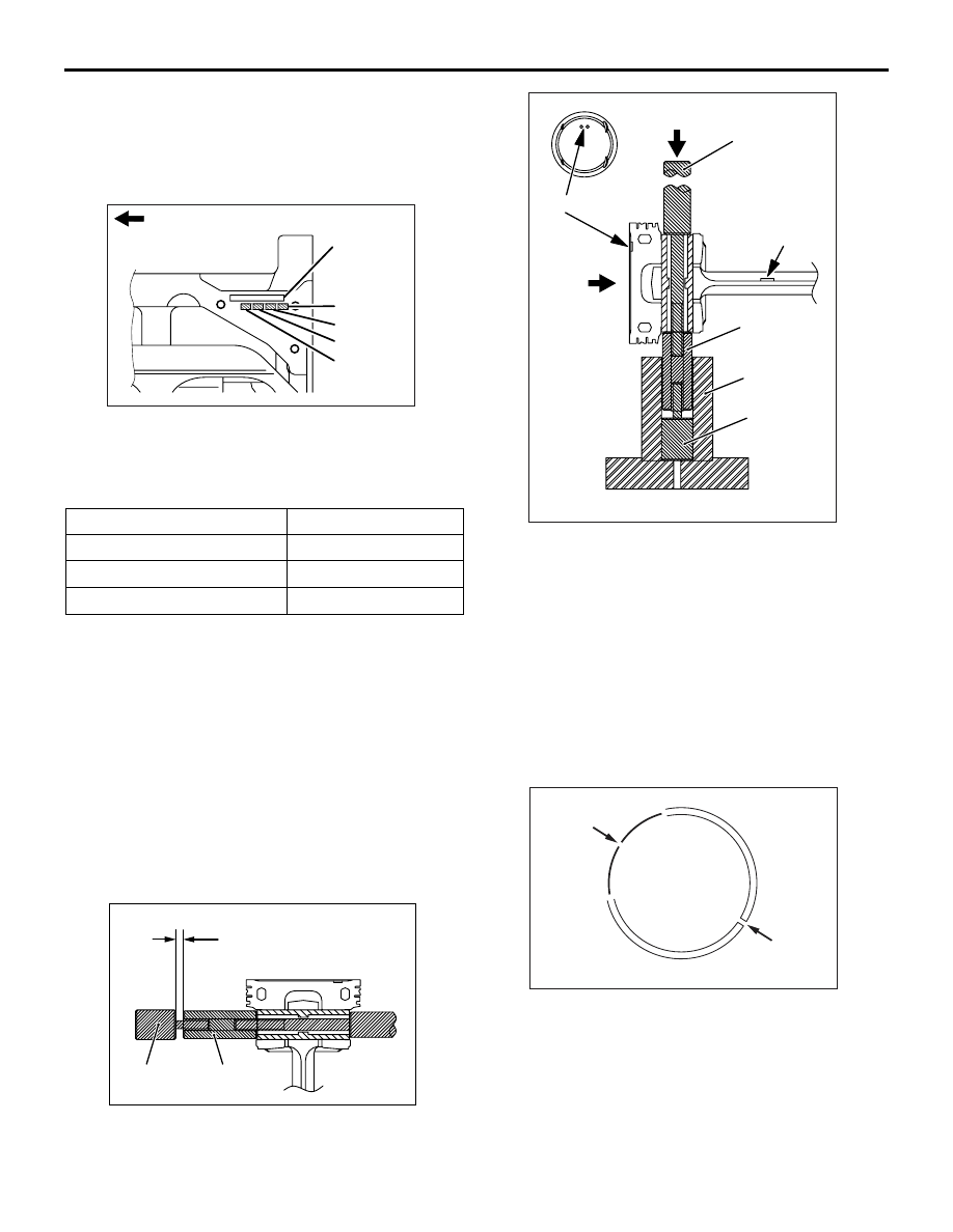
>>A<< PISTON PIN INSTALLATION

1. When replacing a piston, check the cylinder bore 

size mark stamped at the indicated location on the 
cylinder block and select an appropriate 
replacement piston using the following table.

NOTE: The piston size mark is located on the pis-
ton top surface.

2. Insert the special tool Push Rod into the piston 

pin, and install Guide A.

3. Assemble the piston and the connecting rod 

together, ensuring that their front marks are 
aligned with each other.

4. Apply engine oil onto the periphery of the piston 

pin.

5. Insert the piston pin assembled in Step 1 above 

into the piston pin boss. Guide A end of the piston 
pin should be inserted first into the front mark end 
of the boss.

6. Insert Guide B into Guide A with having 1.25 mm 

of the clearance "L" between Guide A and B.

7. Install the piston and connecting rod assembly 

with the tools onto the special tool Piston Setting 
Base, ensuring that the piston front mark faces 
upwards.

8. Using a press, press fit the piston pin. If the force 

required to press fit the piston pin is less than the 
standard value, replace the piston pin (piston 
assembly) or the connecting rod, or both.

Standard value: 7,350 

 17,100 N 

>>B<< OIL RING INSTALLATION

1. Fit the oil ring coil expander and oil ring into the 

piston ring groove.
NOTE: Locate the oil ring and coil expander end 
gaps as shown in the drawing.
NOTE: New coil expander and oil ring are an 
identified by colour marks as follows:

Cylinder bore size mark

Piston size mark

I

A

II

No mark

III

C

AK202923

Crankshaft
bore size mark

Timing belt side

No.4

No.1

No.2

No.3

AB

AK304522

L

Guide A

Guide B

AC

AK501783

P

P

Push rod

Front mark

Front mark

AB

Base

Guide A

Guide B

AK502373

Coil expander 
end gap

Oil ring
end gap

AB

PISTON AND CONNECTING ROD

ENGINE OVERHAUL

11B-60

CAUTION

Use of ring expander to expand the oil ring end 
gap can break the oil ring, unlike other piston 
rings.

2. To install each coil expander, first fit one end of 

the oil ring into the piston groove, then press the 
remaining portion progressively into position by 
finger as shown in the drawing.

3. Make sure that the installed oil ring move 

smoothly in either direction.

>>C<< PISTON RING NO. 2 / PISTON 
RING NO. 1 INSTALLATION

Using a piston ring expander, install the piston rings 
with their identification marks facing up (toward the 
piston crown).

Identification marks:

No.1 ring: 1R
No.2 ring: 2R

NOTE: Each of the available piston rings has a size 
mark as follows:

>>D<< PISTON AND CONNECTING ROD 
ASSEMBLY INSTALLATION

1. Apply engine oil generously to the piston's outside 

surface, piston rings, and oil ring.

2. Align the end gaps of the piston rings and oil ring 

(oil ring and coil expander) as shown in the 
drawing.

3. Insert the piston and connecting rod assembly 

from the top of cylinder with the front mark on the 
crown toward the camshaft sprocket.

4. Not to damage the crank pin, attach a special tool 

Bolt guide (MB992010), to the connecting rod 
bolt.

Size

Colour mark

Standard

No mark

0.50 mm oversize

Red

1.00 mm oversize

Yellow

AK202785

Oil ring end

AD

AK202786

Piston ring 
expander

AC

AK202807

No. 2

AB

No. 1

Size marks

Identification mark

Size

Size mark

Standard No. 1 ring No mark (white paint on 

periphery)

No. 2 ring No mark

0.50 mm oversize

50

1.00 mm oversize

100

AK202730

No. 1

No. 2

AE

Piston pin

Coil expander

Oil ring

AK402300AC

MB992010

Bolt

Connecting rod

PISTON AND CONNECTING ROD

ENGINE OVERHAUL

11B-61

CAUTION

• Do not strike the assembly with a large force. 

Doing so could break the piston rings.

• When striking the assembly into cylinder, do 

not allow it to interfere with the oil jet.

5. Use a piston ring band to hold the piston rings 

compressed when inserting the piston and 
connecting rod assembly into the cylinder. 

>>E<< CONNECTING ROD BEARING 
INSTALLATION

1. When replacing the connecting rod bearing, 

select a bearing of the size appropriate for the 
crankshaft pin diameter in accordance with the 
crankshaft pin and connecting rod bearing 
matching table shown below.

2. Crankshaft pin diameter marks are stamped in the 

indicated locations.

3. Connecting rod bearing identification mark is 

stamped in the indicated location on each 
bearing.

<Bearing selection example>
If the crankshaft pin diameter mark is “I,” select a 
bearing marked “1.”
If the crankshaft pin diameter mark is illegible, 
measure the pin diameter and select a bearing 
with the mark corresponding to the measurement.

4. Install the upper and lower halves of the selected 

bearing on the connecting rod big end and cap, 
respectively.

>>F<< CONNECTING ROD CAP 
INSTALLATION

1. Install the bearing cap on the connecting rod while 

aligning the marks made during disassembly. If 
the connecting rod is new and has no alignment 
mark, assemble it with the cap such that the both 
bearing locating notches are on the same side as 
shown in the drawing.

AK202798

AK202909

Locations of crankshaft pin diameter 
marks

No. 3

No. 1

No. 2

No. 4

AB

AK203964AC

Identification mark

Crankshaft pin

Connecting rod 
bearing

Identification 
mark

Diameter mm

Identification 
mark

I

44.995 

− 45.000 0

II

44.985 

− 44.995 1

III

44.980 

− 44.985 2

AK202813

Cylinder 
number

Bearing 
locating 
notches

AB

AK202821

PISTON AND CONNECTING ROD

ENGINE OVERHAUL

11B-62

2. Make sure that the thrust clearance of the 

connecting rod big end is proper.

Standard value: 0.10 

 0.25 mm

Limit: 0.4 mm

>>G<< CONNECTING ROD CAP NUT 
INSTALLATION

1. The connecting rod cap bolts and nuts are 

tightened using the torque-to-yield method. For 
this reason, each bolt to be reused must be 
checked for elongation before installation. 
Whether or not the bolt has been elongated can 
be determined by running a nut with fingers 
through all the threads of the bolt. If the nut does 
not turn smoothly over all the threads, the bolt has 
been elongated and must be replaced.

2. Apply engine oil to the threads and bearing 

surface of each nut before installation.

3. Finger-tighten the nuts on the bolts, then tighten 

the nuts alternately and repeatedly to install the 
cap properly.

4. Tighten the nuts to a torque of 20 

± 2 N⋅m.

5. Make a paint mark on the head of each nut.

CAUTION

• If the tightening angle is less than 90°, ade-

quate tightness could not be assured.

• If the tightening angle exceeds 94°, loosen the 

nut completely and then perform the tighten-
ing procedure again beginning with the first 
step.

6. Make a paint mark on the bolt at a point 90

° to 94° 

away from the paint mark made on the nut in the 
tightening direction.

7. Turn the nut 90

° to 94° to bring the mark on the 

nut into alignment with that on the bolt.

INSPECTION

M1113008500990

PISTON RING

1. Measure the clearance between each piston ring 

and its groove. If the limit is exceeded, replace the 
ring or piston, or both.

Standard values: 

No. 1 ring: 0.03 

 0.07 mm

No. 2 ring: 0.02 

 0.06 mm

Limits: 0.1 mm

2. Install a piston ring or oil ring side rail into the 

cylinder bore and force it down with the head of a 
piston until the ring is at right angles to the 
cylinder wall. Measure the end gap with a 
thickness gauge.
NOTE: If the end gap is excessive, replace the 
piston ring.

Standard values:

No. 1 ring: 0.20 

 0.30 mm

No. 2 ring: 0.30 

 0.50 mm

Oil ring: 0.10 

 0.40 mm

Limits:

No. 1 ring: 0.8 mm
No. 2 ring: 0.8 mm
Oil ring: 1.0 mm

AK300612

Paint marks

Nut

Bolt

Paint marks

90˚ to 94˚

AC

AK202787

AK202788

Force ring down 
with piston

End gap

Piston ring

AB


Content   ..  90  91  92  93   ..