Mitsubishi Lancer Evolution IX. Manual - part 86


  Index      Mitsubishi     Mitsubishi Lancer Evolution IX - service repair manual


Search            


Content   ..  84  85  86  87   ..


Mitsubishi Lancer Evolution IX. Manual - part 86


WATER PUMP AND WATER HOSE

ENGINE OVERHAUL

11B-35

INSTALLATION SERVICE POINTS
>>A<< O-RING/WATER INLET PIPE 
INSTALLATION

CAUTION

• Never allow any oil or grease to touch the 

O-rings.

• Clamp the water inlet pipe only after installa-

tion of the thermostat case.

Replace the O-rings at both ends of the water inlet 
pipe with new ones. Insert the O-rings into the water 
pump and thermostat housing after wetting their 
peripheries with water.
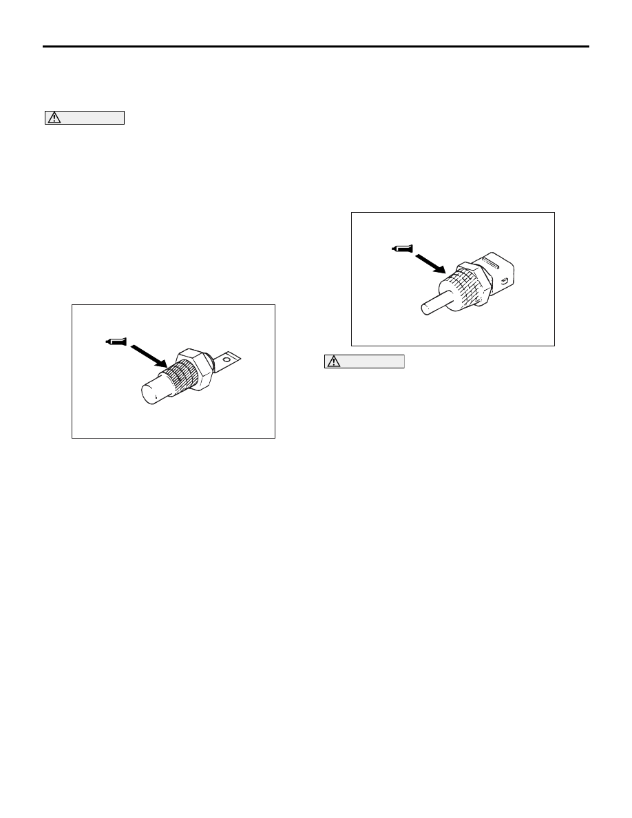
>>B<< ENGINE COOLANT 
TEMPERATURE GAUGE UNIT 
INSTALLATION

1. Remove all old sealant remaining on the threaded 

hole in the engine coolant temperature gauge unit 
and the thermostat housing.

NOTE: A new engine coolant temperature gauge 
unit is coated with sealant. It does not require 
coating with sealant before installation.

2. Apply sealant to the indicated threads of the 

engine coolant temperature gauge unit.

Specified sealant:

3M Nut Locking Part No.4171 or equivalent

>>C<< ENGINE COOLANT 
TEMPERATURE SENSOR INSTALLATION

CAUTION

When using a tool, avoid letting it touch the con-
nector portion which is made of plastic.
1. Remove all old sealant remaining on the threads 

of the engine coolant temperature sensor and in 
the threaded hole in the thermostat housing.

2. Apply sealant to the engine coolant temperature 

sensor's threads indicated in the drawing.

Specified sealant:

3M ATD Part No.8660 or equivalent

AK202800AB

AK202799AB

ROCKER ARMS AND CAMSHAFT

ENGINE OVERHAUL

11B-36

ROCKER ARMS AND CAMSHAFT

REMOVAL AND INSTALLATION

M1113005401179

AK403842AC

30 ± 3 N·m

11 ± 1 N·m

42 ± 2 N·m

30 ± 3 N·m

11 ± 1 N·m

1

2

3

4

5

6

13

14

15

16

17

18

19

20

21

22

23

24

25

26

27

28

29

30

32

20 ± 1 N·m

11 ± 1 N·m

22 ± 4 N·m

14 ± 1 N·m

10 ± 2 N·m

11 ± 1 N·m

31

11 ± 1 N·m

11

22 ± 4 N·m

14 ± 1 N·m

9

10 ± 2 N·m

7

12

8

10

Apply engine oil to
all moving parts
before installation.

Removal steps 

>>

J

<< 1. Camshaft position sensor

2. O-ring

>>

I

<<

3. Cover

>>

I

<<

4. Gasket

>>

H

<< 5. Camshaft position sensing cylinder

>>

G

<< 6. Camshaft position sensor support

>>

J

<< 7. Camshaft position sensor

8. O-ring

>>

I

<<

9. Cover

>>

I

<<

10. Gasket

>>

H

<< 11. Camshaft position sensing cylinder

>>

G

<< 12. Camshaft position sensor support

>>

F

<< 13. Camshaft oil seal

>>

E

<< 14. Bearing cap, rear right

>>

E

<< 15. Bearing cap, rear left

>>

E

<< 16. Bearing cap, front

>>

E

<< 17. Bearing cap No.5

>>

E

<< 18. Bearing cap No.2

>>

E

<< 19. Bearing cap No.3

>>

E

<< 20. Bearing cap No.4

>>

D

<< 21. Camshaft

22. Rocker arm

<<

A

>> >>

C

<< 23. Lash adjuster

24. Oil delivery body
25. Oil feeder control valve
26. O-ring
27. Check valve

>>

B

<< 28. Eye bolt

29. Oil pipe

>>

A

<< 30. Oil feeder control valve filter

31. Oil pipe joint
32. Gasket

Removal steps (Continued)

ROCKER ARMS AND CAMSHAFT

ENGINE OVERHAUL

11B-37

SERVICE POINTS FOR REMOVAL
<<A>> LASH ADJUSTER REMOVAL

CAUTION

When reusing a lash adjuster, it must be washed 
and inspected before installation. (Refer to 

P.11B-39

, the instruction under LASH ADJUSTER 

in the INSPECTION section.) 

INSTALLATION SERVICE POINTS
>>A<< OIL FEEFER CONTROL VALVE 
FILTER INSTALLATION

CAUTION

Install the OCV filter on which no foreign materi-
als, no defects and no deformation are con-
firmed.

>>B<< EYE BOLT INSTALLATION

NOTE: When the oil pipe joint is rotated together with 
the eye bolt at the installation, the oil pump would be 
possibly damaged.
Holding the oil pipe joint with a spanner, tighten the 
eye bolt to the specified torque of 42 

± 2 N⋅m.

>>C<< LASH ADJUSTER INSTALLATION

CAUTION

When reusing a lash adjuster, it must be washed 
and inspected before installation. (Refer to 

P.11B-39

, the instruction under LASH ADJUSTER 

in the INSPECTION section.)
Install the lash adjuster into the rocker arm, being 
careful not to spill the diesel fuel it contains.

>>D<< CAMSHAFT INSTALLATION

CAUTION

• Do not confuse the intake camshaft with the 

exhaust camshaft. 

• As shown in the illustration, the shapes of the 

intake camshaft and the exhaust camshaft are 
different.

>>E<< BEARING CAP INSTALLATION

1. Set each camshaft with its dowel pin at the top.

2. The bearing caps No. 2 to 5 are identical in shape 

for both intake and exhaust camshafts. Check the 
identification mark on each cap before installation.

Identification mark (stamped on front and 

Nos. 2 

 5 bearing caps)

I: intake camshaft
E: exhaust camshaft

3. Remove completely sealant remaining on the 

bearing caps and cylinder head.

AK403894AC

Eye bolt

Oil pipe joint

Spanner

AK501789AB

Intake camshaft

Exhaust camshaft

Timing belt side

AK203979 AC

Dowel pin

AK202870

Cap number

Intake/exhaust 
identification 
letter

AB

ROCKER ARMS AND CAMSHAFT

ENGINE OVERHAUL

11B-38

4. Apply sealant to the surfaces indicated in the 

drawing.

Specified sealant:

3M ATD No.8660 or equivalent

5. Install each bearing cap and tighten its bolts in two 

or three passes.

6. Finally tighten the bolts to 20 

± 1 N⋅m.

7. Check that the rocker arms are correctly installed.
NOTE: Wipe off any squeezed out sealant com-
pletely.

>>F<< CAMSHAFT OIL SEAL 
INSTALLATION

Use the special tool Camshaft oil seal installer 
(MD998713) to drive each oil seal into position in the 
cylinder head.

>>G<< CAMSHAFT POSITION SENSOR 
SUPPORT INSTALLATION

1. Remove completely the FIPG remaining on the 

camshaft position sensor support and cylinder 
head.

2. Apply a 3 

± 1 mm diameter bead of FIPG to the 

indicated surface of the camshaft position sensor 
support.

Specified sealant:

Mitsubishi Genuine Part No.MD970389 or 

equivalent

>>H<< CAMSHAFT POSITION SENSING 
CYLINDER INSTALLATION

1. Turn the exhaust camshaft to the No.1 cylinder 

top dead centre position.
NOTE: The camshaft will slightly turn counter-
clockwise by the force of the exhaust valve spring.

2. Install the camshaft position sensing cylinder with 

the vanes and paint located as shown in the 
drawing.

>>I<< COVER / GASKET INSTALLATION

1. Before the cover and the gasket installations, 

confirm the vanes and paint of the every sensing 
cylinder are in position indicated in the illustration 
with the camshaft on No.1 top dead center of 
compression stroke.

AK202871AB

AK304515

MD998713

AB

AK403895AC

Intake side

Exhaust side

AK501669AB

Vane (small)

Vane (big)

Paint

Intake side

Exhaust side

AK501669AB

Vane (small)

Vane (big)

Paint

Intake side

Exhaust side


Content   ..  84  85  86  87   ..