Mitsubishi Lancer Evolution 7. Manual - part 343


  Index      Mitsubishi     Mitsubishi Lancer Evolution 7 - service repair manual


Search            


Content   ..  341  342  343  344   ..


Mitsubishi Lancer Evolution 7. Manual - part 343


BODY -

Doors

42-33

REMOVAL SERVICE POINTS

A

AWINDOW REGULATOR ASSEMBLY/POWER

WINDOW MOTOR ASSEMBLY REMOVAL

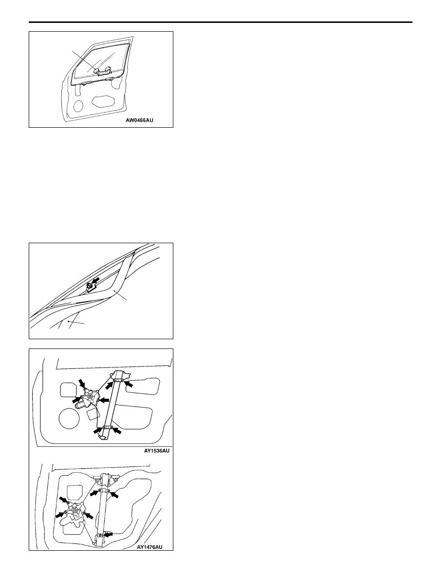
1. Loosen the door window glass assembly mounting bolts.

2. Raise the door window glass assembly, and then adhere

the special tool on the glass as shown in the illustration

to prevent from falling.
CautionFor the door window glass adhered film and

etc., use the special tool from outside the door glass

to prevent unstucking.

3. Remove the power window regulator and motor assembly.

A

BDOOR CENTER SASH REMOVAL

1. Remove only the section of the door outer opening

weatherstrip

2. Remove the center sash upper mounting screws, and

then remove the center sash upper from the door panel.

INSTALLATION SERVICE POINTS

"

AWINDOW REGULATOR ASSEMBLY/POWER

WINDOW MOTOR ASSEMBLY INSTALLATION

When installing the window regulator assembly, tighten he

bolts at the specified torque in the order shown in the

illustration.

MB990480

Door outer opening

weatherstrip

Door center sash

A18X0127

<REAR DOOR>

<FRONT DOOR>

1

2

4

3

5

6

1

2

3

4

5

6

7

BODY -

Doors

BODY -

Doors

42-34

"

BOPERATION CHECK <Vehicles with power

window>

1. Install the glass to the window regulator assembly.

Caution

(1) As fully open position which is programed in the

power window-ECU is released (initialized), the

window regulator assembly should not be

operated until it is installed to the glass.

(2) The clamping prevention function does not

operate the first time that the glass is fully closed.

2. Press the power window switch to fully-open the glass,

and then return the glass toward the fully-close position

about 30 mm each. In the fully-close position, keep on

pressing the power window switch for 0.5 second or more.
NOTE

This operation will program the power window-ECU.

INSPECTION

POWER WINDOW RELAY CONTINUITY CHECK

Battery voltage

Terminal No.

y

g

1

3

4

5

Not applied
Applied

Power window

relay

1 2 3

4

5

BODY -

Doors

42-35

DOOR HANDLE AND LATCH

REMOVAL AND INSTALLATION

Pre-removal Operation

Door Trim Removal (Refer to P.42-27.)

Post-installation Operation
D

Door Inside Handle Looseness Check (Refer to

P.42-24.)

D

Door Outside Handle Looseness Check (Refer to

P.42-23.)

D

Door Trim Installation (Refer to P.42-27.)

<FRONT DOOR>

<REAR DOOR>

3

5

4

7

2

6

1

5.9 ± 1.0 N·m

8.9 ± 1.9 N·m

2

1

7

5

6

2.5 ± 0.5 N·m

2.5 ± 0.5 N·m

Door handle and door latch

removal steps

"

CA 1. Door inside handle

D

Waterproof film (Refer to P.42-27.)

D

Door window glass lower runchan-

nel (Refer to P.42-38, 39.)

D

Door center sash (Refer to

P.42-32.)

2. Door outside handle

3. Key cylinder

"

BA 4. Lower sash

5. Door latch assembly

6. Link

Door check removal steps

D

Waterproof film (Refer to P.42-27.)

"

AA 7. Door check

INSTALLATION SERVICE POINTS

"

ADOOR CHECK INSTALLATION

Install with the following identification marks upward.

Items

Identification mark

Front door

Left side

21L

Right side

21R

Rear door

Left side

36L

Right side

36R

Identification

mark

BODY -

Doors

BODY -

Doors

42-36

"

BLOWER SASH INSTALLATION

Be sure to install the lower sash to the window rear sash

(at door) securely.

"

CDOOR INSIDE HANDLE INSTALLATION

1. Install the inside lock cable to the door inside handle

as follows:

(1) Install the inner cable end in the inside lock cable

to the clip in the door inside handle.

(2) Turn the inside lock knob to the door lock position.

(3) Install the outer cable end to the door inside handle

securely.

(4) Install the clip to the inner cable.

2. Install the inside handle rod to the door inside handle.

3. Install the door inside handle to the door.

INSPECTION

DOOR LOCK ACTUATOR CHECK

Front door

<Left side (Driver’s side)>

Rod position

Terminal No.

Rod operation

1

2

3

4

6

LOCK

LOCK to UNLOCK

UNLOCK

UNLOCK to LOCK

LOCK
UNLOCK

<Left side (Passenger’s side)>

Rod position

Terminal No.

Rod operation

4

6

LOCK

LOCK to UNLOCK

UNLOCK

UNLOCK to LOCK

<Right side (Driver’s side)>

Rod position

Terminal No.

Rod operation

1

2

3

4

6

LOCK

LOCK to UNLOCK

UNLOCK

UNLOCK to LOCK

LOCK
UNLOCK

<Right side (Passenger’s side)>

Rod position

Terminal No.

Rod operation

p

4

6

p

LOCK

LOCK to UNLOCK

UNLOCK

UNLOCK to LOCK

Door inside

handle

Inner cable

Clip

Outer cable

end

Inside

handle rod

<Front door>

B

Unlock

<Left side>

View B

Lock

<Right side>

View A

Unlock

Lock

A


Content   ..  341  342  343  344   ..