Mitsubishi Lancer Evolution VI. Manual - part 120


  Index      Mitsubishi     Mitsubishi Lancer Evolution VI - service repair manual


Search            


Content   ..  118  119  120  121   ..


Mitsubishi Lancer Evolution VI. Manual - part 120


  – Ducts

HEATER AND MANUAL
AIR CONDITIONER

55-32

9

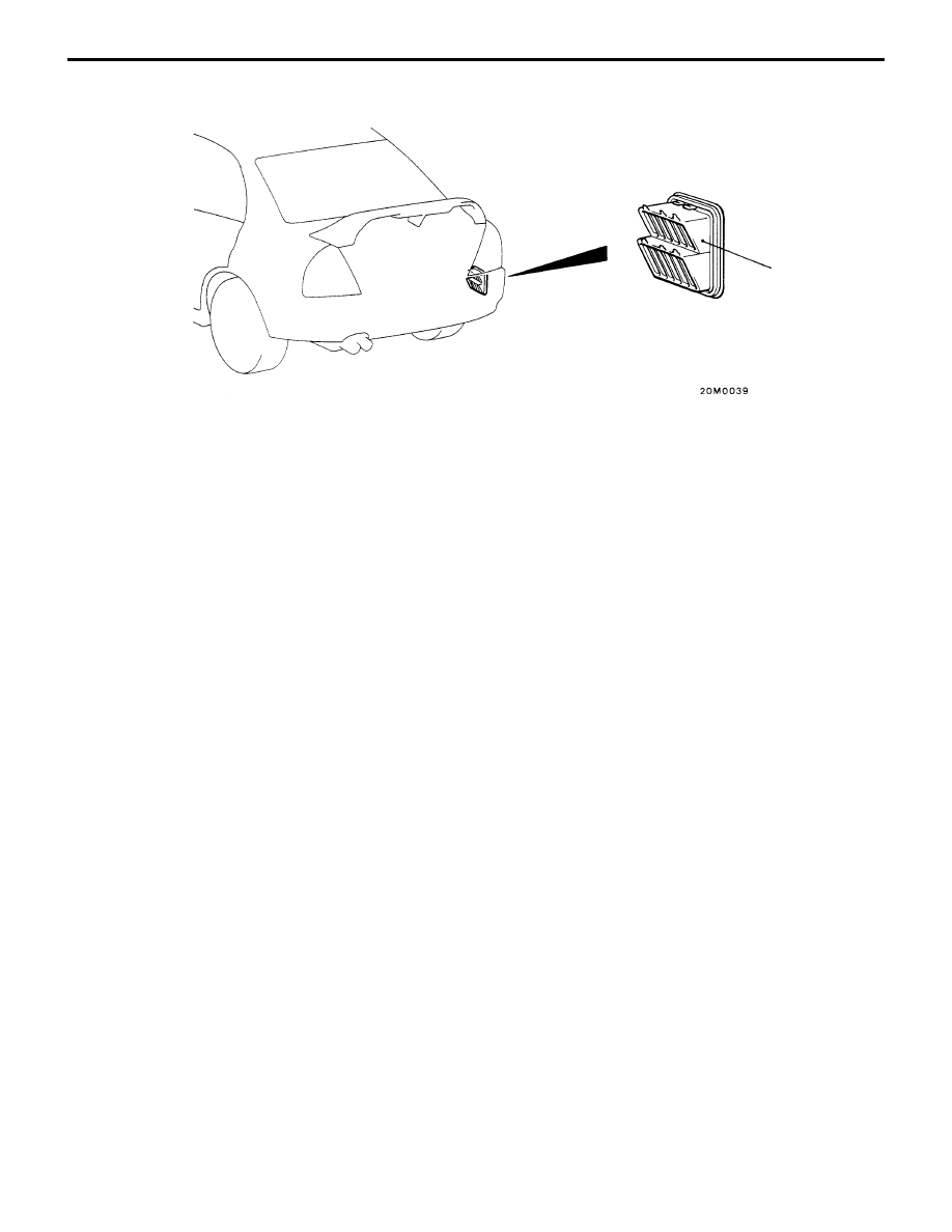
Rear ventilation duct removal steps

D

Rear bumper assembly

D

Trunk side trim

9. Rear ventilation duct

FULL-AUTOMATIC AIR CONDITIONER – 

General / Service Specifications /
Lubricants / Special Tools

55-33

FULL-AUTOMATIC AIR CONDITIONER

GENERAL

OUTLINE OF CHANGE

D

The following service procedures have been established.

SERVICE SPECIFICATIONS

Items

Standard value

Idle speed  r/min

750 

"

 50

Idle-up speed  r/min

850 

"

 50

Air gap (Compressor)  mm

0.4 – 0.6

Air mix damper potentiometer
resistance k

MAX. HOT position

4.82

resistance  k

MAX. COOL position

0.18

Outlet air changeover damper
potentiometer resistance k

DEF position

0.18

potentiometer resistance  k

FACE position

4.82

LUBRICANTS

Items

Specified lubricants

Quantity

Compressor oil  m

ȏ

SUN PAG 56

120 – 140

Each connection of refrigerant line

SUN PAG 56

As required

Refrigerant  g

R134a (HFC-134a)

555 – 595

SPECIAL TOOLS

Tool

Number

Name

Use

MB991502

MUT-

II


sub-assembly

Inspection of full-automatic air conditioner

MB991529

Diagnosis code
check harness

Inspection of full-automatic air conditioner
using a voltmeter

FULL-AUTOMATIC AIR CONDITIONER – 

Troubleshooting

55-34

TROUBLESHOOTING

STANDARD FLOW OF DIAGNOSTIC TROUBLESHOOTING

Refer to GROUP 00 – How to Use Troubleshooting/Inspection Service Points.

DIAGNOSIS FUNCTION

DIAGNOSIS CODES CHECK

Connect the MUT-

II

 or a voltmeter to the diagnosis connector (16-pin), then check diagnosis codes.

(Refer to GROUP 00 – How to Use Troubleshooting/Inspection Service Points.)

ERASING DIAGNOSIS CODES

Refer to GROUP 00 – How to Use Troubleshooting/Inspection Service Points.

INSPECTION CHART FOR DIAGNOSIS CODES

Code No.

Diagnosis item

Reference
page

11

Inside air temperature sensor system (open circuit)

55-34

12

Inside air temperature sensor system (short circuit)

55-34

13

Outside air temperature sensor system (open circuit)

55-35

14

Outside air temperature sensor system (short circuit)

55-35

15

Heater water temperature sensor system (open circuit)

55-36

16

Heater water temperature sensor system (short circuit)

55-36

21

Air thermo sensor system (open circuit)

55-37

22

Air thermo sensor system (short circuit)

55-37

31

Potentiometer system of air mix damper assembly

55-38

32

Potentiometer system of air outlet changeover damper assembly

55-39

41

Drive system of air mix damper motor assembly

55-40

42

Drive system of air outlet changeover damper motor assembly

55-40

INSPECTION PROCEDURES FOR DIAGNOSIS CODES

Code No.11 Inside air temperature sensor system (open
circuit)

Probable cause

This diagnosis code is output if the power supply line or input line of the inside
air temperature sensor inside A/C-ECU is open-circuited and no signal is input
from the inside air temperature sensor to A/C-ECU.

D

Malfunction of the A/C-ECU

Replace the A/C-ECU.

Code No.12 Inside air temperature sensor system (short
circuit)

Probable cause

This diagnosis code is output if the power supply line or input line of the inside
air temperature sensor inside A/C-ECU is short-circuited and inside air
temperature sensor power supply voltage signals are input to A/C-ECU.

D

Malfunction of the A/C-ECU

Replace the A/C-ECU.

FULL-AUTOMATIC AIR CONDITIONER – 

Troubleshooting

55-35

Code No.13 Outside air temperature sensor system (open
circuit)

Probable cause

This diagnosis code is output if the power supply line or input line of the outside
air temperature sensor is open-circuited and no signal is input from the outside
air temperature sensor to A/C-ECU.

D

Malfunction of the outside air temperature sensor

D

Malfunction of connector, harness

D

Malfunction of the A/C-ECU

Outside air temperature sensor check (Refer to P.55-62.)

NG

Replace

OK

Measure at the outside air temperature sensor connector A-35.

D

Disconnect the connector, and measure at the harness
side connector.

D

Voltage between terminal (2) and body earth
OK: 5 V

NG

Check the following connectors:
B-15, B-16

NG

Repair

OK

Check the trouble symptom.

NG

Check the harness between the outside air temperature sensor
and the A/C-ECU.

NG

Repair

OK

Replace the A/C-ECU.

OK

Measure at the A/C-ECU connector B-04.

D

Connect the connector.

D

Voltage between terminal (7) and body earth
OK: 2.3  – 2.9 V

NG

Check the following connectors:
A-15, B-04

NG

Repair

OK

Check the trouble symptom.

NG

Check the harness between the outside air temperature sensor
and the A/C-ECU, and repair if necessary.

OK

Check the following connector: B-04

NG

Repair

OK

Check the trouble symptom.

NG

Replace the A/C-ECU.

Code No.14 Outside air temperature sensor system (short
circuit)

Probable cause

This diagnosis code is output if the power supply line or input line of the outside
air temperature sensor is short-circuited and outside air temperature sensor power
supply voltage signals are input to A/C-ECU.

D

Malfunction of the outside air temperature sensor

D

Malfunction of connector, harness

D

Malfunction of the A/C-ECU

Outside air temperature sensor check (Refer to P.55-62.)

NG

Replace

OK

Measure at the A/C-ECU connector B-04.

D

Connect the connector.

D

Voltage between terminal (7) and body earth
OK: 2.3  – 2.9 V

NG

Check the harness between the outside air temperature sensor
and the A/C-ECU, and repair if necessary.

OK

Replace the A/C-ECU.


Content   ..  118  119  120  121   ..