Mitsubishi Lancer Evolution VI. Manual - part 72


  Index      Mitsubishi     Mitsubishi Lancer Evolution VI - service repair manual


Search            


Content   ..  70  71  72  73   ..


Mitsubishi Lancer Evolution VI. Manual - part 72


ABS  – 

On-vehicle Service

35B-38

6.

If the result of inspection is abnormal, correct according to the “Diagnosis Table”.

Diagnosis Table

No.

MUT-

II


display

Operation

Judgement 
– Normal

Judgement 
– Abnormal

Probable
cause

Remedy

01

FR valve

(1) Depress brake pedal

to lock wheel.

(2) Using the MUT-

II

,

select the wheel to be
checked and force the

Brake force
released for 3
seconds after
locking.

Wheel does
not lock when
brake pedal is
depressed.

Clogged
brake line
other than
hydraulic unit

Check and
clean brake
line

02

FL valve

checked and force the
actuator to operate.

(3) Turn the selected

wheel using brake
force tester or manual-
ly to check the change

Clogged
hydraulic
circuit in
hydraulic unit

Replace
hydraulic unit
assembly

03

RR valve

ly to check the change
of brake force.

Brake force is
not released

Incorrect
hydraulic unit
brake tube
connection

Connect
correctly

04

RL valve

Hydraulic unit
solenoid valve
not function-
ing correctly

Replace
hydraulic unit
assembly

7.

After inspection, turn the ignition switch off and remove the MUT-

II

.

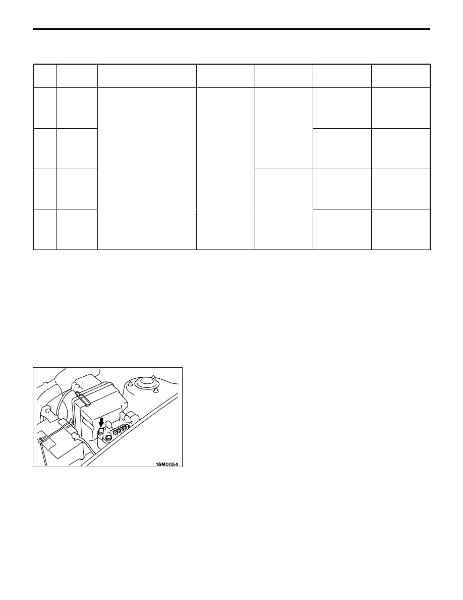
REMEDY FOR A FLAT BATTERY

When booster cables are used to start the engine when the
battery is completely flat and then the vehicle is immediately
driven without waiting for the battery to recharge itself to
some extent, the engine may misfire, and driving might not
be possible.
This happens because ABS consumes a great amount of
current for its self-check function; the remedy is to either
allow the battery to recharge sufficiently, or to remove the
fusible link for ABS circuit, thus disabling the anti-skid brake
system. The ABS warning lamp will illuminate when the fusible
link (for ABS) is removed.
After the battery has sufficiently recharged, install the fusible
link (for ABS) and restart the engine; then check to be sure
the ABS warning lamp is not illuminated.

ABS  – 

On-vehicle Service

35B-39

ABS MOTOR RELAY CONTINUITY CHECK

Checking condition

Terminal No.

1

2

3

4

5

Power is not supplied

Power is supplied

ABS VALVE RELAY CONTINUITY CHECK

Checking condition

Terminal No.

1

2

3

4

5

6

Power is not supplied

Power is supplied

Valve relay

Motor relay

ABS  – 

Master Cylinder and Brake Booster

35B-40

MASTER CYLINDER AND BRAKE BOOSTER

REMOVAL AND INSTALLATION

Refer to GROUP 35A.

MASTER CYLINDER
DISASSEMBLY AND REASSEMBLY

Master cylinder kit

11

14

13

12

14

13

15

1

4

2

3

6

8

9

5

7

10

12

15

13

14

Brake fluid: DOT3 or DOT4

11

Disassembly steps

1. Reservoir cap assembly
2. Reservoir cap
3. Diaphragm
4. Filter
5. Brake fluid level sensor
6. Float
7. Reservoir stopper bolt

8. Reservoir tank
9. Reservoir seal

A

A

"

10. Piston stopper bolt

11. Gasket

A

A

"

12. Piston stopper ring
13. Primary piston assembly
14. Secondary piston assembly
15. Master cylinder body

DISASSEMBLY SERVICE POINTS

A

A

"

PISTON STOPPER BOLT / STOPPER RING
REMOVAL

Remove the piston stopper bolt and stopper ring, while
depressing the primary piston assembly.

NOTE
Shown at left is the stopper ring removal manner.

ABS  – 

Hydraulic Unit

35B-41

HYDRAULIC UNIT

REMOVAL AND INSTALLATION

Pre-removal Operation

D

Brake Fluid Draining

Post-installation Operation

D

Brake Fluid Supplying and Air Bleeding

D

Hydraulic Unit Checking (Refer to P.35B-37.)

 15 Nm

1

2

3

4

5

2

2

Removal steps

1. Harness connector

"

A

A

2. Brake pipe connection
3. Connector bracket

A

A

"

4. Hydraulic unit assembly
5. Hydraulic unit bracket


Content   ..  70  71  72  73   ..