Mitsubishi Lancer Evolution VI. Manual - part 39


  Index      Mitsubishi     Mitsubishi Lancer Evolution VI - service repair manual


Search            


Content   ..  37  38  39  40   ..


Mitsubishi Lancer Evolution VI. Manual - part 39


MPI  – 

Troubleshooting

13-44

INSPECTION PROCEDURE 32

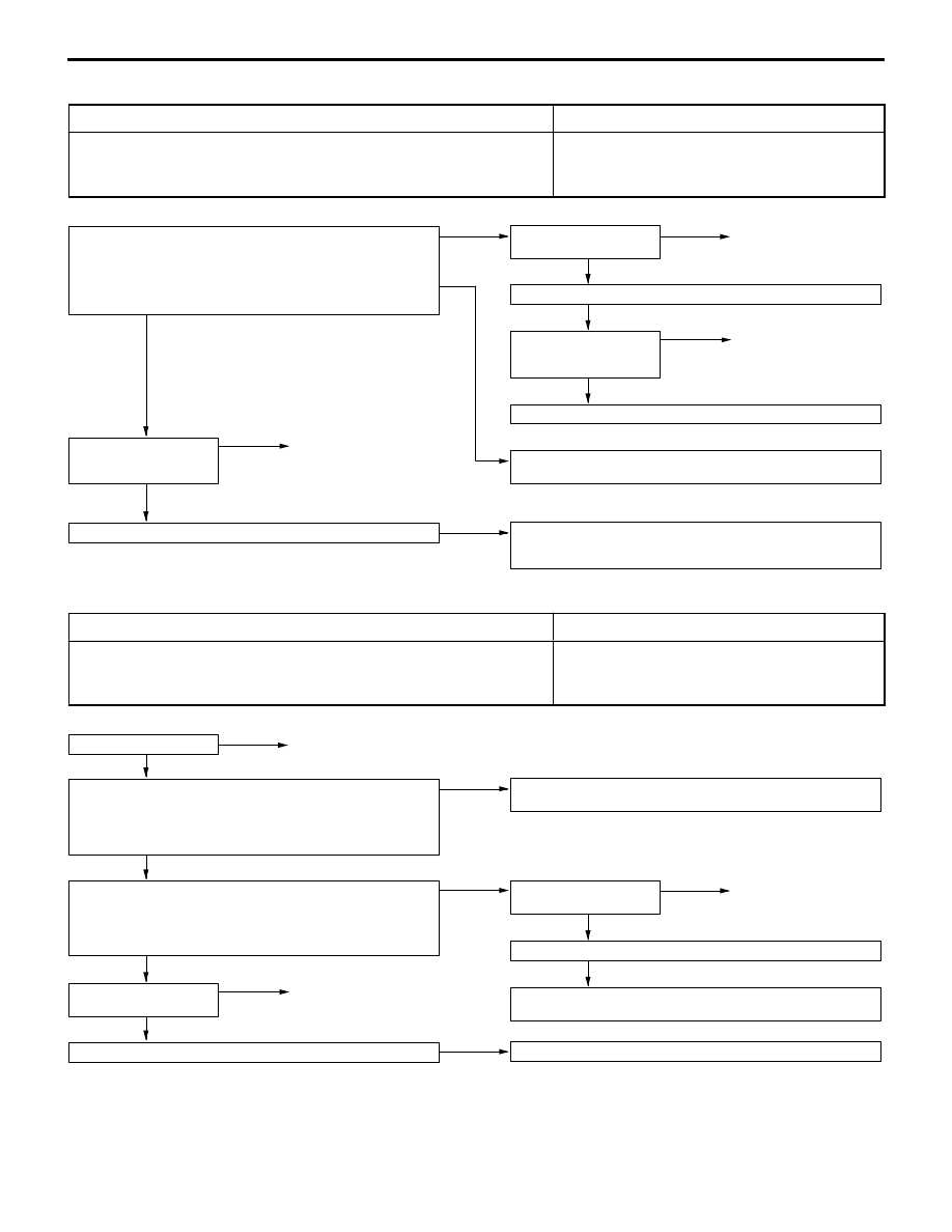
Ignition circuit system

Probable cause

The engine-ECU interrupts the ignition coil primary current by turning the power transistor
inside the engine-ECU ON and OFF.

D

Malfunction of ignition switch.

D

Improper connector contact, open or short-circuited
harness wire

D

Malfunction of the engine-ECU

Measure at the ignition coil connectors A-110, A-111.

D

Disconnect the connector and measure at the harness side.

1. Voltage between 1 and earth (Ignition switch: ON)

OK: System voltage

2. Continuity between 2 and earth

OK: Continuity

1. NG

Check the following
connectors:
 B-65, B-76

NG

Repair

OK

Check trouble symptom.

NG

Check the harness wire
between ignition coil and
ignition switch connector.

NG

Repair

OK

Check the ignition switch.

2. NG

Check the harness wire between ignition coil connector and earth,
and repair if necessary.

OK

Check the following
connectors:
A-110, A-111

NG

Repair

OK

Check trouble symptom.

NG

Check ignition coil and power transistor unit system. (Refer to
P.13-16, INSPECTION PROCEDURE FOR DIAGNOSIS CODE
44.)

INSPECTION PROCEDURE 33

Idle speed control (ISC) servo (Stepper motor) system

Probable cause

The engine-ECU controls the intake air volume during idling by opening and closing
the servo valve located in the bypass air passage.

D

Malfunction of ISC servo

D

Improper connector contact, open or short-circuited
harness wire

D

Malfunction of the engine-ECU

Check the ISC servo.

NG

Replace

OK

Measure at the ISC servo connector A-18.

D

Disconnect the connector and measure at the harness side.

D

Voltage between 2 and earth, and 5 and earth (Ignition switch:
ON)
OK: System voltage

NG

Check the harness wire between control relay and ISC servo con-
nector, and repair if necessary.

OK

Measure at the engine-ECU connector B-59.

D

Disconnect the connector, measure at the harness side.

D

Voltage between each of 4, 5, 17, 18 and earth (Ignition switch:
ON)
OK: System voltage

NG

Check the following
connector:
 A-18

NG

Repair

OK

Check trouble symptom.

NG

Check harness wire between engine-ECU and ISC servo connector,
and repair if necessary.

OK

Check the following
connector:
 B-59

NG

Repair

OK

Check trouble symptom.

NG

Replace the engine-ECU.

MPI  – 

Troubleshooting

13-45

INSPECTION PROCEDURE 34

Fuel pressure control valve system

Probable cause

The fuel pressure control valve switches the pressure introduction into the fuel pressure
regulator between the intake manifold and atmosphere.

D

Malfunction of solenoid valve

D

Improper connector contact, open or short-circuited
harness wire

D

Malfunction of engine-ECU

NG

Replace the engine-ECU.

OK

Check trouble symptom.

NG

Check the harness wire between engine-ECU and solenoid valve
connector, and repair if necessary.

OK

Check trouble symptom.

OK

Check the following connector: B-59

NG

Repair

OK

Measure at the engine-ECU connector B-59.

D

Disconnect the connector, and measure at the harness side.

D

Voltage between 3 and earth 
(Ignition switch: ON)
OK: System voltage

NG

Check the following connector: A-12

NG

Repair

NG

Check the harness wire between control relay and solenoid valve
connector, and repair if necessary.

OK

Measure at the fuel pressure control valve connector A-12.

D

Disconnect the connector, and measure at the harness side.

D

Voltage between 1 and earth 
(Ignition switch: ON)
OK: System voltage

Check the fuel pressure control valve.

NG

Replace

INSPECTION PROCEDURE 35

Waste gate solenoid valve

Probable cause

The waste gate solenoid valve controls the boost pressure introduced into the waste
gate actuator in the turbocharger.

D

Malfunction of solenoid valve

D

Improper connector contact, open or short-circuited
harness wire

D

Malfunction of engine-ECU

NG

Replace the engine-ECU.

OK

Check trouble symptom.

NG

Check the harness wire between engine-ECU and solenoid valve
connector, and repair if necessary.

OK

Check trouble symptom.

OK

Check the following connector: B-59

NG

Repair

OK

Measure at the engine-ECU connector B-59.

D

Disconnect the connector, and measure at the harness side.

D

Voltage between 11 and earth 
(Ignition switch: ON)
OK: System voltage

NG

Check the following connector: A-23

NG

Repair

NG

Check the harness wire between control relay and solenoid valve
connector, and repair if necessary.

OK

Measure at the waste gate solenoid valve connector A-23.

D

Disconnect the connector, and measure at the harness side.

D

Voltage between 2 and earth 
(Ignition switch: ON)
OK: System voltage

Check the waste gate solenoid valve. 
(Refer to Group 15 – On-vehicle service.)*

NG

Replace

NOTE
*:

Refer to Workshop Manual for LANCER EVOLUTION-IV and EVOLUTION-V (Pub. No. S9806CNCP9).

MPI  – 

Troubleshooting

13-46

INSPECTION PROCEDURE 36

Secondary air control solenoid valve system

Probable cause

The secondary air control solenoid valve switches the pressure introduction into the
secondary air valve between the intake manifold and atmosphere.

D

Malfunction of solenoid valve

D

Improper connector contact, open or short-circuited
harness wire

D

Malfunction of engine-ECU

NG

Replace the engine-ECU.

OK

Check trouble symptom.

NG

Check the harness wire between engine-ECU and solenoid valve
connector, and repair if necessary.

OK

Check trouble symptom.

NG

Check the harness wire between control relay and solenoid valve
connector, and repair if necessary.

OK

Check trouble symptom.

OK

Check the following connector: B-59

NG

Repair

OK

Measure at the engine-ECU connector B-59.

D

Disconnect the connector, and measure at the harness side.

D

Voltage between 6 and earth 
(Ignition switch: ON)
OK: System voltage

NG

Check the following connectors:
A-127, A-88

NG

Repair

OK

Measure at the secondary air control solenoid connector A-127.

D

Disconnect the connector, and measure at the harness side.

D

Voltage between 1 and earth 
(Ignition switch: ON)
OK: System voltage

NG

Check the following connector: A-88

NG

Repair

Check the secondary air control solenoid valve. 
(Refer to Group 15 – INTAKE AND EXHAUST.)*

NG

Replace

NOTE
*:

Refer to Workshop Manual for LANCER EVOLUTION-IV and EVOLUTION-V (Pub. No. S9806CNCP9).

MPI  – 

Troubleshooting

13-47

INSPECTION PROCEDURE 37

MUT-

II

: Inspection of no initial combustion

MUT-

II

 Data list

16 engine-ECU power supply voltage (Refer to P.13-57.)

NG

Check the power supply and ignition switch-IG system. 
(Refer to P.13-35, INSPECTION PROCEDURE 24.)

OK

Does the camshaft rotate at the engine cranking? 
(When oil filler cap is removed.)

No

Check timing belt for breakage.

Yes

MUT-

II

 Self-Diag code

Are diagnosis codes displayed?

Yes

Refer to P.13-8, INSPECTION CHART FOR DIAGNOSIS CODES.

No

MUT-

II

 Data list

22 Crank angle sensor

OK: Cranking speed is displayed.

NG

Check the crank angle sensor system. 
(Refer to P.13-11, INSPECTION PROCEDURE FOR DIAGNOSIS
CODE 22.)

OK

MUT-

II

 Actuator test

07 Fuel pump (Refer to P.13-61.)

NG

Check the fuel pump system. 
(Refer to P.13-36, INSPECTION PROCEDURE 25.)

OK

MUT-

II

 Data list

21 Engine coolant temperature sensor (Refer to P.13-57.)

NG

Check the engine coolant temperature sensor system. 
(Refer to P.13-10, INSPECTION PROCEDURE FOR DIAGNOSIS
CODE 21.)

INSPECTION PROCEDURE 38

Ignition system: Inspection of no initial combustion.

OK

Check the ignition timing when cranking.

OK: Approx. 5

_

BTDC

NG

Check that the crank angle sensor and the timing belt cover are
installed properly.

NG

Check the ignition circuit system. 
(Refer to P.13-44, INSPECTION PROCEDURE 32.)

Check by connecting a timing light to the spark plug cable.

OK: Timing light flashes during cranking.


Content   ..  37  38  39  40   ..