Mitsubishi Lancer Evolution VI. Manual - part 26
ENGINE –
Alternator
11-79
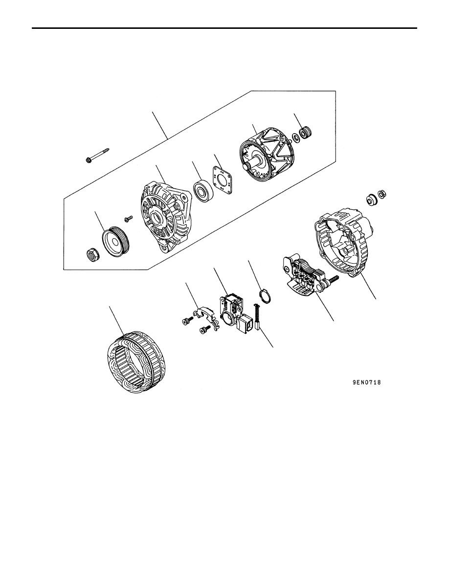
ALTERNATOR
DISASSEMBLY AND REASSEMBLY
1
2
3
4
5
6
7
8
9
10
11
12
13
14
Disassembly steps
A
A
"
1. Front bracket assembly
A
B
"
2. Alternator pulley
"
B
A
3. Rotor
4. Rear bearing
5. Bearing retainer
6. Front bearing
7. Front bracket
A
C
"
8. Stator
9. Plate
A
C
" "
A
A
10. Regulator assembly
11. Brush
12. Slinger
13. Rectifier
14. Rear bracket