Mitsubishi Eclipse / Eclipse Spyder (2000-2002). Service and repair manual - part 676
SRS AIR BAG DIAGNOSIS
TSB Revision
SUPPLEMENTAL RESTRAINT SYSTEM (SRS)
52B-31
DTC SET CONDITIONS
•
These DTC are output if the voltage between the
IG1 terminals (fuse No.13 or No.5 circuit) and
ground is lower than a predetermined value for a
continuous period of five second or more.
However, if the vehicle condition returns to
normal, DTC numbers 41 or 42 will be
automatically erased, and the SRS warning light
will switch off.
TROUBLESHOOTING HINTS
•
Damaged wiring harnesses or connectors
•
Malfunction of the SRS-ECU
DIAGNOSIS
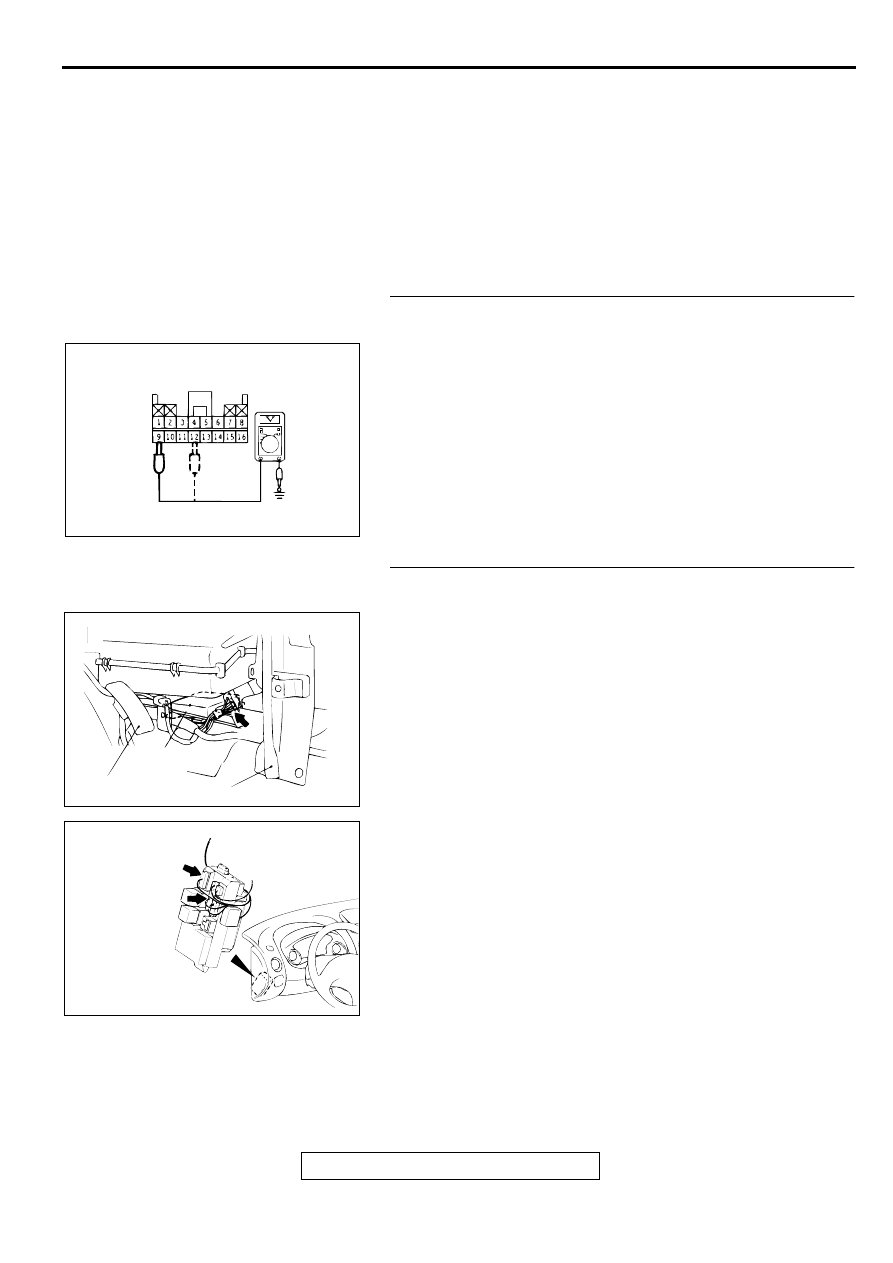
STEP 1. Check the ignition switch (IG1) line at the SRS-
ECU connector C-72 by backprobing.
(1) Do disconnect the connector C-72.
(2) Connect the negative battery terminal.
(3) Turn the ignition switch to "ON" position.
(4) Measure the voltage between terminal 12 (for DTC 41) or 9
(for DTC 42) and the ground by backprobing.
•
Voltage should be 9 volts or more
Q: Is the voltage 9 volts or more?
YES : Go to Step 3.
NO : Go to Step 2.
STEP 2. Check the harness wires between the ignition
switch (IG1) and SRS-ECU connector C-72.
NOTE: After inspecting intermediate connectors C-101 and C-
107, inspect the wiring harness. If intermediate connectors are
damaged, repair or replace them. Refer to GROUP 00E,
Harness Connector Inspection
Q: Are harness wires between the ignition switch (IG1) and
SRS-ECU connector C-72 in good condition?
YES : Go to Step 5.
NO : Repair them. Then go to Step 5.
AC000367AC
C-72 CONNECTOR HARNESS SIDE VIEW
AC000358AD
SRS-ECU
ACCELERATOR PEDAL
CENTER REINFORCEMENT(LH)
CONNECTOR: C-72
AC000366AC
CONNECTOR: C-101, C-107
C-101
C-107
JUNCTION
BLOCK
(FRONT VIEW)