Mitsubishi Eclipse / Eclipse Spyder (2000-2002). Service and repair manual - part 609


  Index      Mitsubishi     Mitsubishi Eclipse / Eclipse Spyder (2000-2002). Service and repair manual


Search            


Content   ..  607  608  609  610   ..


Mitsubishi Eclipse / Eclipse Spyder (2000-2002). Service and repair manual - part 609


POWER STEERING GEAR BOX ASSEMBLY

TSB Revision

POWER STEERING

37A-31

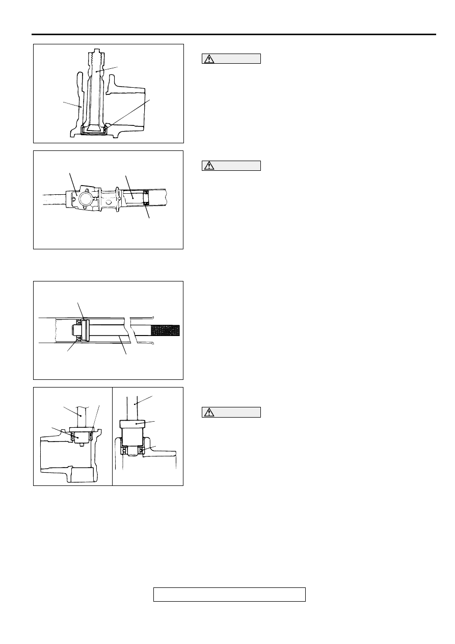
<<J>> NEEDLE ROLLER BEARING REMOVAL

CAUTION

Do not open special tool MB991120 excessively to prevent 
damaging housing interior.
Use special tool MB991120 to remove the needle roller bearing 
from the rack housing.

<<K>> OIL SEAL REMOVAL

CAUTION

Be careful not to damage the inner surface of the rack 
cylinder of the gear housing.
Use a piece of pipe or similar tool to remove the oil seal from 
the gear housing.

ASSEMBLY SERVICE POINTS

>>A<< OIL SEAL INSTALLATION
1. Apply a coating of the MITSUBISHI POWER STEERING 

FLUID to the both sides of the oil seal.

2. Using special tools MB991199 and MB991197, press the oil 

seal into the rack housing.

>>B<< NEEDLE ROLLER BEARING/BALL BEARING 
INSTALLATION

CAUTION

Press-fit straight. Valve housing is aluminum, and may 
become deformed if Press-fit on an angle.
1. Apply MITSUBISHI POWER STEERING FLUID to housing, 

bearing and oil seal press fitting surface.

2. Press fit needle roller bearing with special tools MB990938 

and MB991202.

ACX01150 AB

VALVE
HOUSING

MB991120

NEEDLE
ROLLER
BEARING

AC001004

OIL SEAL

AB

PIPE OR SIMILAR TOOL

GEAR HOUSING

AC001005

MB991197

AB

OIL SEAL

MB991199

ACX01153

NEEDLE
ROLLER BEARING

MB990938

MB991202

MB991202

BALL
BEARING

AC

MB990938

POWER STEERING GEAR BOX ASSEMBLY

TSB Revision

POWER STEERING

37A-32

>>C<< OIL SEAL/O-RING INSTALLATION
1. Apply a coating of the MITSUBISHI POWER STEERING 

FLUID to the outside of the oil seal and O-ring.

2. Use special tool MB990927 to press fit oil seal until it 

touches rack bush end.

>>D<< RACK INSTALLATION

CAUTION

Do not close the vent hole in the rack with grease.
1. Apply a coating of multipurpose grease to the rack teeth 

face.

2. Cover rack serrations with special tool MB991213.

3. Apply MITSUBISHI POWER STEERING FLUID to special 

tool MB991213.

4. Align center of oil seal with rack to prevent retainer spring 

from slipping. Slowly insert rack from power cylinder side.

>>E<< RACK BUSHING INSTALLATION

CAUTION

Do not allow oil seal retainer spring to slip out.
Wrap the rack end with vinyl tape, apply a coating of the 
MITSUBISHI POWER STEERING FLUID, and then install the 
rack bushing and rack stopper.

>>F<< CIRCLIP INSTALLATION

CAUTION

Insert circlip to rack stopper hole whilst turning rack 
stopper clockwise.
Insert circlip to rack stopper hole through cylinder hole. Turn 
rack stopper clockwise and insert circlip firmly.

ACX01156AC

OIL SEAL

O-RING

MB990927

RACK
BUSH

ACX01154 AB

SEAL RING, O-RING

VENT HOLE

ACX01155

MB991213

AB

OIL SEAL

ACX01157

RACK BUSH

AB

VINYL TAPE

RACK

ACX01158

CIRCLIP

SLOT

SLOT

AB

CIRCLIP

POWER STEERING GEAR BOX ASSEMBLY

TSB Revision

POWER STEERING

37A-33

>>G<< OIL SEAL/BALL BEARING INSTALLATION
Apply a coating of the MITSUBISHI POWER STEERING 
FLUID to the outside of the oil seal/ball bearing. Using special 
tools MB990938 and MB991203, press the oil seal/ball bearing 
into the valve housing.

>>H<< SEAL RING INSTALLATION
Because the seal rings expand after installation, tighten after 
installing by using special tool MB991317 to compress the 
rings, or press down by hand.

>>I<< OIL SEAL INSTALLATION

CAUTION

To eliminate a seal malfunction at the valve housing 
alignment surface, the upper surface of the oil seal should 
project outward approximately 1 mm (0.04 inch) from the 
housing edge surface.
Using special tool MB991152, press the oil seal into the valve 
housing.

>>J<< END PLUG INSTALLATION
1. Apply the 3M

 AAD Part number 8672, 8679, 8678, 8661, 

8663 or equivalent to the threaded part of the end plug.

2. Secure the threaded portion of the end plug at two places by 

using a punch.

>>K<< RACK SUPPORT COVER/JAM NUT INSTALLATION
1. Position rack at its center.

2. Apply the 3M

 AAD Part number 8672, 8679, 8678, 8661, 

8663 or equivalent to the threaded part of the ruck support 
cover.

ACX01159AC

MB990938

MB991203

OIL SEAL

MB991203

BEARING

MB990938

ACX01160 AB

MB991317

ACX01161

HOUSING

AB

OIL
SEAL

APPROXIMATELY
1 mm(0.04 in)

MB991152

ACX01162 AB

END PLUG

END PLUG

POWER STEERING GEAR BOX ASSEMBLY

TSB Revision

POWER STEERING

37A-34

3. Use special tool MB991204 to tighten rack support cover to 

13 

±

 2 N

m (109 

±

 21 in-lb).

4. Turn the rack support cover by 10 degree counterclockwise.

5. Use special tool MB991204 to hold the rack support cover, 

and then tighten the jam nut to 59 

±

 10 N

m (44 

±

 7 ft-lb).

>>L<< TOTAL PINION TORQUE ADJUSTMENT

CAUTION

When adjusting, set at the highest value of the standard 
value range.

Be sure there is no ratcheting or catching when 
operating the rack towards the shaft.

Measure the total pinion torque through the whole 
stroke of the rack.

NOTE: If the total pinion toque cannot be adjusted to the 
standard value within the specified return angle, check the rack 
support cover components and replace any parts if necessary.
1. Using special tool MB990228 or MB991006, rotate the 

pinion shaft at the rate of one rotation in four to six seconds 
to check the total pinion torque and the change in torque.

Standard value:
Total pinion torque: 0.8 

 1.9 mm (6.9 

 16.5 in-lb)

[Change in torque: 0.7 N

m (6.1 in-lb) or less]

2. If the total pinion torque or the change in torque is outside 

the standard value, return the rack support cover within 0 
degree angle to 30 degree angle, and adjust again.

>>M<< TAB WASHER/TIE ROD INSTALLATION
After installing tie rod to rack, fold tab washer end (two 
locations) to tie rod notch.

AC001009 AB

MB991204

AC000996 AB

MB990228
OR 
MB991006

ACX01163 AB


Content   ..  607  608  609  610   ..