Mitsubishi Eclipse / Eclipse Spyder (2000-2002). Service and repair manual - part 605
ON-VEHICLE SERVICE
TSB Revision
POWER STEERING
37A-15
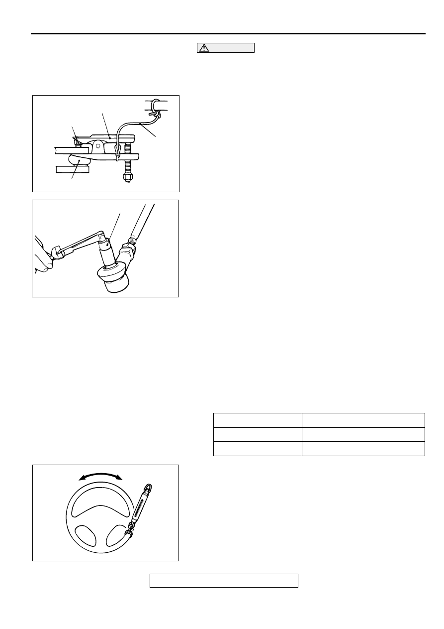
CAUTION
•
Loosen the nut from the ball joint instead of removing
it.
•
Hang special tool MB991113 or MB990635 with ropes to
prevent it from falling.
1. Use special tool MB991113 or MB990635 to disconnect the
ball joint.
2. Move the ball joint stud several times and install the nut on
the stud. Measure the ball joint breakaway torque with
special tool MB990326.
Standard value: 0.5
−
2.5 N
⋅
m (4.4
−
22.1 in-lb)
3. If the breakaway torque exceeds the standard value, replace
the tie rod end.
4. If the breakaway torque is under the standard value, check
the ball joint for end play or ratcheting. If no end play or
ratcheting, the ball joint can be re-used.
5. Tighten the nut to the specified torque and install a new
cotter pin.
Tightening torque: 29
±
4 N
⋅
m (21
±
4 ft-lb)
STATIONARY STEERING EFFORT CHECK
M1372001700075
1. With the vehicle stopped on a flat and paved surface, turn
the steering wheel to the straight ahead position.
2. Start the engine and check the engine idle speed.
Standard value:
3. Attach a spring scale to the outer circumference of the
steering wheel and measure the steering force required to
turn the steering wheel from the straight ahead position to
the left and right (within a range of 1.5 turns). Also check to
be sure that there is no significant fluctuation of the required
steering effort.
Standard value:
Steering effort: 30 N (6.7 lb) or less
Fluctuation allowance: 5.9 N (1.33 lb) or less
ACX01123AB
NUT
BALL JOINT
CORD
MB991113 OR MB990635
ACX01129 AB
MB990326
ENGINE
ENGINE IDLE SPEED r/min
2.4L Engine
750
±
100
3.0L Engine
700
±
100
AC000987