Mitsubishi Eclipse / Eclipse Spyder (2000-2002). Service and repair manual - part 581


  Index      Mitsubishi     Mitsubishi Eclipse / Eclipse Spyder (2000-2002). Service and repair manual


Search            


Content   ..  579  580  581  582   ..


Mitsubishi Eclipse / Eclipse Spyder (2000-2002). Service and repair manual - part 581


ANTI-SKID BRAKING SYSTEM (ABS) DIAGNOSIS

TSB Revision

ANTI-LOCK BRAKING SYSTEM (ABS)

35B-15

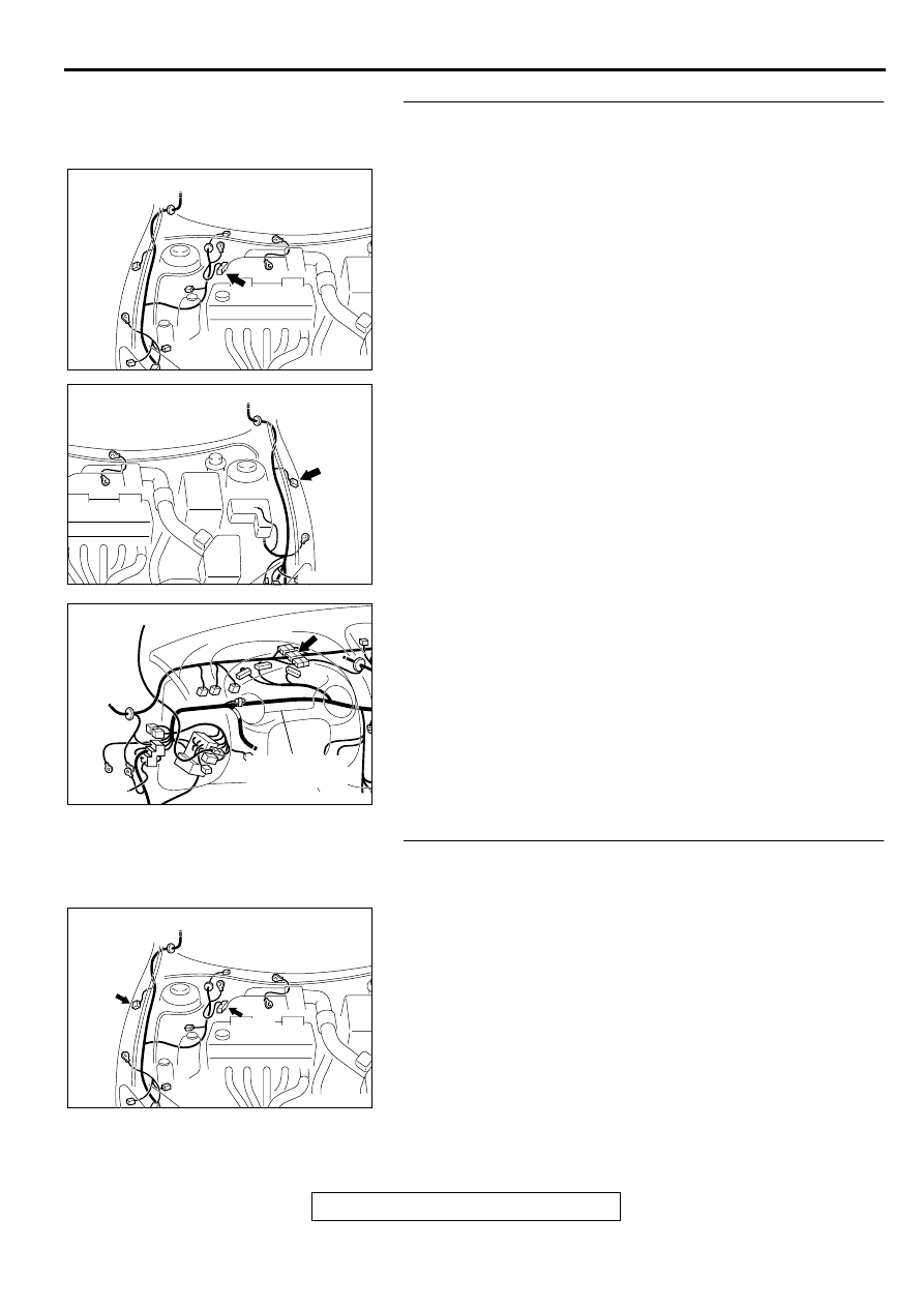
STEP 2. Check the harness wires between the ABS-ECU 
connector A-02 and the wheel speed sensor <front: LH> 
connector A-22.
NOTE: After inspecting the intermediate connector C-06, 
inspect the wires. If the intermediate connector C-06 is 
damaged, repair or replace it. Refer to GROUP 00E, Harness 
Connector Inspection 

P.00E-2

. If the connector has been 

repaired or replaced, go to Step 8.

Q: Is any of the harness wires between the ABS-ECU 

connector A-02 and the wheel speed sensor <front: LH> 
connector A-22 damaged?
YES : 
Repair it and go to Step 8.
NO :  Go to Step 3.

STEP 3. Check the harness wires between the ABS-ECU 
connector A-02 and the wheel speed sensor <front: RH> 
connector A-37.
Q: Is any of the harness wires between the ABS-ECU 

connector A-02 and the wheel speed sensor <front: RH> 
connector A-37 damaged?
YES : 
Repair it and then go to Step 8.
NO :  Go to Step 4.

AC001985

CONNECTOR: A-02

AD

AC002137AB

CONNECTOR: A-22

AC001989 BH

CONNECTOR: C-06

COMBINATION
METER

AC001985

CONNECTORS: A-02, A-37

AC

A-02

A-37

ANTI-SKID BRAKING SYSTEM (ABS) DIAGNOSIS

TSB Revision

ANTI-LOCK BRAKING SYSTEM (ABS)

35B-16

STEP 4. Check the harness wires between the ABS-ECU 
connector A-02 and the wheel speed sensor connectors D-
08 <rear: RH> or D-09 <rear: LH>.
NOTE: After inspecting the intermediate connector C-90, C-94 
or D-16, inspect the wires. If the intermediate connector C-90, 
C-94 or D-16 is damaged, repair or replace it. Refer to GROUP 
00E, Harness Connector Inspection 

P.00E-2

If the connector 

has been repaired or replaced, go to Step 8.

Q: Is any of the harness wires between the ABS-ECU 

connector A-02 and the wheel speed sensor connector 
D-08 <rear: RH> or D-09 <rear: LH> damaged?
YES : 
Repair it and then go to Step 8.
NO :  Go to Step 5.

AC001985

CONNECTOR: A-02

AD

AC004408AB

CONNECTOR: C-90

AC004410AB

CONNECTOR: C-94

AC004426AB

CONNECTORS: D-08, D-09, D-16

D-09

D-16

D-08

ANTI-SKID BRAKING SYSTEM (ABS) DIAGNOSIS

TSB Revision

ANTI-LOCK BRAKING SYSTEM (ABS)

35B-17

STEP 5. Check each wheel speed sensor output voltage.
Refer to 

P.35B-45

.

Output Voltage:

When measured with a voltmeter: 42 mV or more

When measured with oscilloscope (maximum voltage): 200 
mV or more

Q: Does the voltage meet the specification?

YES : Replace the hydraulic unit (integrated with ABS-ECU) 

and then go to Step 8.

NO :  Go to Step 6.

STEP 6. Check the wheel speed sensors or ABS rotors.
Refer to 

P.35B-53

. If there is a damage in any of the following 

check items, replace the wheel speed sensor or the ABS rotor.

Check items:

Wheel speed sensor internal resistance

Standard value: 1.28 

 1.92 k

Insulation between the wheel speed sensor body and the 
connector terminals

Toothed ABS rotor

Q: Is any of the wheel speed sensors or ABS rotors 

damaged?
YES : 
 Replace the faulty part and then go to Step 8.
NO :  Go to Step 7.

STEP 7. Check the wheel bearings.
Refer to GROUP 26, Front Hub Assembly 

P.26-7

, and GROUP 

27, Rear Axle Hub 

P.27-5

.

Q: Is any of the wheel bearings damaged?

YES :  Replace it and then go to Step 8.
NO :  Go to Step 8.

STEP 8. Check the diagnostic trouble codes.

Q: Do the diagnostic trouble code 15 reset?

YES : Go to Step 1.
NO :  This diagnosis is complete.

ANTI-SKID BRAKING SYSTEM (ABS) DIAGNOSIS

TSB Revision

ANTI-LOCK BRAKING SYSTEM (ABS)

35B-18

DTC 38: Stoplight Switch System

Stoplight Switch Circuit


Content   ..  579  580  581  582   ..