Mitsubishi Eclipse / Eclipse Spyder (2000-2002). Service and repair manual - part 539
SPECIAL TOOLS
TSB Revision
FRONT AXLE
26-5
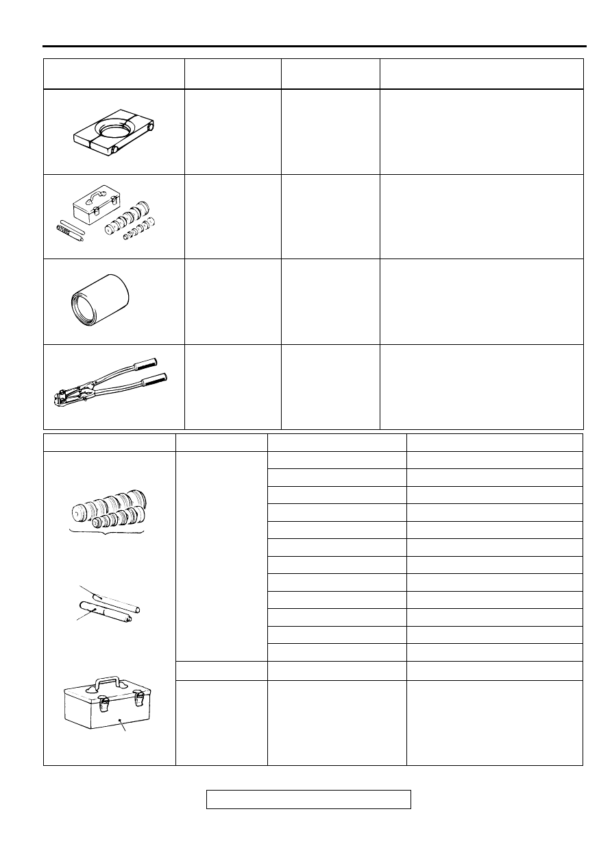
MB991248 or
MB998801
Inner shaft
remover
MD998348-01
Inner shaft removal
MB990925
Bearing and oil
seal installer set
MB990925-01 or
General service
tool
Bearing removal and dust seal
installation
MB990890
Rear suspension
bush base
MB990890-01
Oil seal installation
MB991561
Boot band
crimping tool
MB991561
Resin boot band installation
TOOL
TOOL NUMBER
AND NAME
SUPERSESSION APPLICATION
MB991248
MB990925
MB990890
MB991561
TOOL
TYPE
TOOL NUMBER
O D mm (in)
A
MB990926
39.0 (1.54)
MB990927
45.0 (1.77)
MB990928
49.5 (1.95)
MB990929
51.0 (2.00)
MB990930
54.0 (2.13)
MB990931
57.0 (2.24)
MB990932
61.0 (2.40)
MB990933
63.5 (2.50)
MB990934
67.5 (2.66)
MB990935
71.5 (2.81)
MB990936
75.5 (2.97)
MB990937
79.0 (3.11)
B
MB990938
−
C
MB990939
−
ACX02372
A
B
C
BRASS BAR
BAR (SNAP-IN TYPE)
TOOL BOX
MB990925
AB
INSTALL ADAPTER