Mitsubishi Eclipse / Eclipse Spyder (2000-2002). Service and repair manual - part 529


  Index      Mitsubishi     Mitsubishi Eclipse / Eclipse Spyder (2000-2002). Service and repair manual


Search            


Content   ..  527  528  529  530   ..


Mitsubishi Eclipse / Eclipse Spyder (2000-2002). Service and repair manual - part 529


TRANSAXLE

TSB Revision

AUTOMATIC TRANSAXLE OVERHAUL

23B-47

83.Install the two O-rings.

84.Install the torque converter housing and then tighten its 18 

mounting bolts to the specified torque.

Tightening torque: 48 

±

 6 N

m (35 

±

 4 ft-lb)

85.Insert the two O-rings into the grooves of the manual control 

lever shaft.

86.Install the manual control lever shaft and parking pawl rod.

87.Align hole "A" with the groove in the manual control lever 

shaft. Insert the manual control lever shaft roller into hole 
"A".

88.Insert the new seal rings in the grooves of the accumulator 

pistons.

NOTE: The piston and seal ring are common parts.

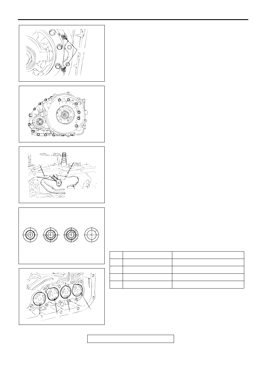
89.Identify the accumulator spring and insert it and the 

accumulator piston into each hole of the transaxle case.

NOTE: Accumulator springs are identified as shown in the 
illustration.

NO. NAME

IDENTIFICATION "BLUE-ING"

1

For low-reverse brake None

2

For underdrive clutch

Half

3

For second brake

Whole surface

4

For overdrive clutch

None

AKX01024AB

O-RINGS

AKX01104

AKX00962AB

MANUAL 
CONTROL LEVER 
SHAFT ROLLER

PARKING 
PAWL ROD

MANUAL CONTROL
LEVER SHAFT

AKX01078

IDENTIFICATION OF ACCUMULATOR SPRING

1

2

3

4

NOTE: THE SHADOWS ARE THE AREAS 
OF IDENTIFICATION "BLUE-ING."

AB

AKX01008

4

3

2

AB

1

TRANSAXLE

TSB Revision

AUTOMATIC TRANSAXLE OVERHAUL

23B-48

90.Install the strainer and second brake retainer oil seal.

91.Insert a new O-ring to the groove of the solenoid valve 

harness connector.

92.Insert the solenoid valve harness connector into the hole 

from the inside of the transaxle case so it is oriented as 
shown in the illustration. Then secure the snap ring to the 
connector groove.

93.Install a steel ball into each of the two holes in the top face 

of the valve body (outside valve body).

94.Install the valve body and gasket to the transaxle case.

Make sure that the manual valve's pin is in the groove in the 
detent plate of the manual control lever.

95.Install the fluid temperature sensor.

96.Install the 28 valve body mounting bolts, and tighten to the 

specified torque.

Tightening torque: 11 

±

 1 N

m (95 

±

 9 in-lb)

AKX01007AB

SECOND BRAKE
RETAINER OIL SEAL

STRAINER

AKX00961AB

SNAP RING

AKX01005

AKX00960

FLUID TEMPERATURE SENSOR

AB

TRANSAXLE

TSB Revision

AUTOMATIC TRANSAXLE OVERHAUL

23B-49

97.Connect the solenoid valve harness connectors to the valve 

body connectors and the fluid temperature sensor 
connector.

98.Install the manual control shaft detent and tighten the bolt to 

the specified torque.

Tightening torque: 6 

±

 1 N

m (52 

±

 9 in-lb)

99.Apply a 2 mm (0.08 inch) diameter bead of sealant 

(MITSUBISHI Genuine Part number MD974421 or 
equivalent) to the valve body cover in the area shown.

NOTE: Be sure to install the case quickly while the sealant is 
wet (with 15 minutes).

NOTE: After installation, keep the sealed area away from 
the oil for approximately one hour.

100.Install the valve body cover, and then tighten its mounting 

bolts to the specified torque.

Tightening torque: 11 

±

 1 N

m (95 

±

 9 in-lb)

NO. PARTS TO BE 

CONNECTED

SOLENOID VALVE HARNESS

CABLE COLOR CONNECTOR 

HOUSING 
COLOR

1

Underdrive solenoid 
valve

White, red, red

Black

2

Overdrive solenoid 
valve

Orange, red

Black

3

Low-reverse solenoid 
valve

Brown, yellow

Milky white

4

Second solenoid valve Green, red, red

Milky white

5

Torque converter 
clutch control solenoid 
valve

Blue, yellow, 
yellow

Black

6

Fluid temperature 
sensor

Black, red

Black

AKX01004

AKX01103AB

MANUAL CONTROL 
SHAFT DETENT

AKX01079

AKX01003

TRANSAXLE

TSB Revision

AUTOMATIC TRANSAXLE OVERHAUL

23B-50

101.Install the speedometer gear and tighten the bolt to the 

specified torque.

Tightening torque: 5 

±

 1 N

m (43 

±

 9 in-lb)

102.Install the park/neutral position switch and tighten the bolt 

to specified torque.

Tightening torque: 11 

±

 1 N

m (95 

±

 9 in-lb)

103.Install the manual control lever and tighten the nut to 

specified torque.

Tightening torque: 22 

±

 3 N

m (16 

±

 2 ft-lb)

104.Install the input shaft speed sensor and output shaft speed 

sensor and tighten the bolt to the specified torque.

Tightening torque: 11 

±

 1 N

m (95 

±

 9 in-lb)

105.Install the oil cooler feed tube together with new gaskets 

and tighten the eye bolts to the specified torque.

Tightening torque: 30 

±

 3 N

m (22 

±

 2 ft-lb)

106.Tighten the oil cooler feed pipe clamp bolt.

Tightening torque: 11 

±

 1 N

m (95 

±

 9 in-lb)

107.Install the oil dipstick.

108.Install the cable support bracket.

Tightening torque: 23 

±

 3 N

m (17 

±

 2 ft-lb)

109.Install the roll stopper brackets.

Tightening torque: 69 

±

 10 N

m (51 

±

 7 ft-lb)

CAUTION

Apply ATF to the oil pump drive hub before installing the 
torque converter. Be careful not to damage the oil seal lip 
when installing the torque converter.
110.Install the torque converter, and secure it so that the shown 

dimension "A" meets the reference value.

Reference value:

Approximately 12.2 mm (0.48 inch) <F4A42>
Approximately 9.4 mm (0.37 inch) <F4A51>

AKX01102

AKX01100AB

PARK/NEUTRAL 
POSITION 
SWITCH

MANUAL CONTROL
LEVER

AKX01087AB

OUTPUT SHAFT 
SPEED SENSOR

INPUT SHAFT SPEED 
SENSOR

AKX01081

A

AB


Content   ..  527  528  529  530   ..