Mitsubishi Eclipse / Eclipse Spyder (2000-2002). Service and repair manual - part 395


  Index      Mitsubishi     Mitsubishi Eclipse / Eclipse Spyder (2000-2002). Service and repair manual


Search            


Content   ..  393  394  395  396   ..


Mitsubishi Eclipse / Eclipse Spyder (2000-2002). Service and repair manual - part 395


EMISSION CONTROL

TSB Revision

ENGINE AND EMISSION CONTROL

17-99

3. Stop the engine. Remove the Tee-fitting and the hand 

vacuum pump.

4. Connect the hand vacuum pump directly to the EGR valve.

5. Start the engine and run at idle until warm.

6. The engine idling speed should be rough when a vacuum of 

29 kPa (8.7 in Hg) or more is applied to the EGR valve.

7. If engine idles rough, EGR passage is open and the system 

is OK. If engine idle is not rough, the EGR passage and the 
valve must be checked for restrictions. Perform the EGR 
valve check. Then repeat the EGR system check.

VACUUM CONTROL VALVE CHECK

M1173002700044

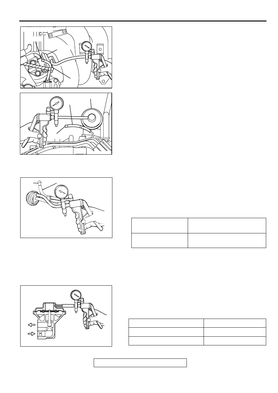
1. Disconnect the vacuum hose (white stripe) from the vacuum 

control valve and connect the hand vacuum pump to the 
vacuum control valve.

2. Plug the end of the removed vacuum hose.

3. Start the engine and run at idle.

4. Check the vacuum condition.

EGR VALVE CHECK

M1173002800041

1. Remove the EGR valve and inspect for sticking, carbon 

deposits, etc. If found, clean with a suitable solvent so that 
the valve seats correctly.

2. Connect a hand vacuum pump to the EGR valve.

3. Apply 67 kPa (20 in Hg) of vacuum, and check to be sure 

that the vacuum is maintained.

4. Apply a vacuum and check the passage of air by blowing 

through one side of the EGR passage.

AKX01318

PLUG

EGR VALVE

BLACK

AB

<2.4L ENGINE>

AKX01319 AB

EGR VALVE

BLACK

PLUG

<3.0L ENGINE>

ENGINE CONDITION

NORMAL VACUUM 
CONDITION

Idling

Approximately 21.3 

 24.0 kPa 

(6.3 - 7.1 in Hg)

AKX01320

WHITE STRIPE

PLUG

AB

VACUUM

PASSAGE OF AIR

5.3 kPa (1.6 in Hg) or less

Air is not blown out

29 kPa (8.7 in Hg) or more

Air is blown out

AKX00348

EMISSION CONTROL

TSB Revision

ENGINE AND EMISSION CONTROL

17-100

NOTE: Passage of air should be checked by blowing the 
valve port.

5. Reinstall the EGR valve, using a new gasket, and tighten to 

the specified torque.

Tightening torque:

<2.4L engine> 19 

±

 3 N

m (14 

±

 2 ft-lb) 

<3.0L engine> 22 

±

 4 N

m (16 

±

 3 ft-lb) 

EGR PORT VACUUM CHECK

M1173002900048

1. Disconnect the vacuum hose (green stripe) from the throttle 

body EGR vacuum nipple and connect a hand vacuum 
pump to the nipple.

2. Start the engine.

3. Measure engine vacuum at idle.

Standard value: 51 kPa (15 in Hg) or more

4. Reset the vacuum pump to "0" (Release vacuum).

5. Using a stop watch, measure how long it takes for the 

vacuum gauge to reach 51 kPa (15 in Hg).

Standard value: 1.0 second or less

6. If it takes more than 1.0 second for the gauge to reach 51 

kPa (15 in Hg), the EGR may be restricted and should be 
cleaned.

EGR SOLENOID CHECK

M1173003100045

1. Disconnect the vacuum hose from the EGR solenoid.

NOTE: When disconnecting the vacuum hose, always make 
sure that it can be reconnected at its original position.

2. Disconnect the harness connector.

AKX01322

EGR PORT
VACUUM NIPPLE

<2.4L ENGINE>

AB

AKX01323

EGR PORT
VACUUM NIPPLE

<3.0L ENGINE>

AB

AKX00350

1.0 SECOND

VACUUM

RESET

TIME

AB

EMISSION CONTROL

TSB Revision

ENGINE AND EMISSION CONTROL

17-101

3. Connect a hand vacuum pump to nipple (A) of the EGR 

solenoid. (Refer to the illustration at left.)

4. Check airtightness by applying a vacuum with voltage 

applied directly from the battery to the EGR solenoid and 
without applying voltage.

5. Measure the resistance between the terminals of the EGR 

solenoid.

Standard value: 29 

 35 

 [at 20

°

C (68

°

F)]

6. Replace the solenoid if resistance is out of specification.

VOLUME AIR FLOW SENSOR CHECK

M1173007900087

<2.4L ENGINE>

To inspect the sensor, refer to GROUP 13A (2.4L), Multiport 
Fuel Injection (MFI) Diagnosis - Diagnostic Trouble Code Chart 

P.13A-20

.

<3.0L ENGINE>

To inspect the sensor, refer to GROUP 13B (3.0L), Multiport 
Fuel Injection (MFI) Diagnosis - Diagnostic Trouble Code Chart 

P.13B-18

.

ENGINE COOLANT TEMPERATURE SENSOR 
CHECK

M1173008100084

<2.4L ENGINE>

To inspect the sensor, refer to GROUP 13A (2.4L), Multiport 
Fuel Injection (MFI) Diagnosis - Diagnostic Trouble Code Chart 

P.13A-20

.

<3.0L ENGINE>

To inspect the sensor, refer to GROUP 13B (3.0L), Multiport 
Fuel Injection (MFI) Diagnosis - Diagnostic Trouble Code Chart 

P.13B-18

.

BATTERY POSITIVE 
VOLTAGE

NORMAL CONDITION

Not applied

Vacuum leaks

Applied

Vacuum maintained

AKX00351

A

B

AB

AKX00352

EMISSION CONTROL

TSB Revision

ENGINE AND EMISSION CONTROL

17-102

CRANKSHAFT POSITION SENSOR CHECK

M1173008300044

<2.4L ENGINE>

To inspect the sensor, refer to GROUP 13A (2.4L), Multiport 
Fuel Injection (MFI) Diagnosis - Diagnostic Trouble Code Chart 

P.13A-20

.

<3.0L ENGINE>

To inspect the sensor, refer to GROUP 13B (3.0L), Multiport 
Fuel Injection (MFI) Diagnosis - Diagnostic Trouble Code Chart 

P.13B-18

.

EVAPORATIVE EMISSION CANISTER AND FUEL TANK PRESSURE RELIEF 
VALVE

REMOVAL AND INSTALLATION

M1173004800081

Pre-removal and Post-installation Operation
Fuel Tank Assembly Removal and Installation (Refer to 
GROUP 13C 

P.13C-6

.)

AC002235

1

2

3

4

5

6

7

8

9

10

AB

REMOVAL STEPS

1. PROTECTOR
2. CANISTER UPPER BRACKET
3. CANISTER ASSEMBLY
4. VENT HOSE
5. OVER VENT VALVE MODULE

6. BRACKET
7. VENT PIPE
8 . VENT HOSE
9. VENT HOSE
10. VAPOR HOSE

REMOVAL STEPS (Continued)


Content   ..  393  394  395  396   ..