Mitsubishi Eclipse / Eclipse Spyder (2000-2002). Service and repair manual - part 326


  Index      Mitsubishi     Mitsubishi Eclipse / Eclipse Spyder (2000-2002). Service and repair manual


Search            


Content   ..  324  325  326  327   ..


Mitsubishi Eclipse / Eclipse Spyder (2000-2002). Service and repair manual - part 326


MULTIPORT FUEL INJECTION (MFI) DIAGNOSIS

TSB Revision

MULTIPORT FUEL INJECTION (MFI) <3.0L ENGINE>

13B-503

DIAGNOSIS

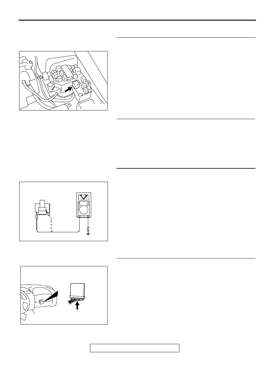
STEP 1. Check connector A-18X at starter relay for 
damage.
Q: Is the connector in good condition?

YES : Go to Step 2.
NO :  Repair or replace it. Refer to GROUP 00E, Harness 

Connector Inspection (

P.00E-2

).Then confirm that the 

malfunction symptom is eliminated.

STEP 2. Check the starter relay.
Refer to GROUP 16, Starting system 

 On-vehicle Service 


Starter relay Check (

P.16-23

).

Q: Are there any abnormalities?

YES : Go to Step 3.
NO :  Repair or replace it. Then confirm that the malfunction 

symptom is eliminated.

STEP 3. Check the power supply voltage at starter relay 
connector A-18X.
(1) Disconnect the connector A-18X and measure at the 

harness side.

(2) Turn the ignition switch to the "START" position.
(3) Measure the voltage between terminal 3, 4 and ground.

Voltage should be battery positive voltage.

(4) Turn the ignition switch to the "LOCK" (OFF) position.

Q: Is the voltage normal?

YES : Go to Step 4.
NO :  Repair harness wire between ignition switch 

connector C-87 terminal 5 and starter relay connector 
A-18X terminal 3,4 because of open circuit. Then 
confirm that the malfunction symptom is eliminated.

STEP 4. Check connector C-58 at ECM for damage.
Q: Is the connector in good condition?

YES : Go to Step 5.
NO :  Repair or replace it. Refer to GROUP 00E, Harness 

Connector Inspection (

P.00E-2

). Then confirm that 

the malfunction symptom is eliminated.

AK000356

CONNECTOR : A-18X

AB

AK000382AB

A-18X HARNESS
SIDE CONNECTOR

1

2

4

3

5

AK000357

CONNECTOR:C-58

AD

MULTIPORT FUEL INJECTION (MFI) DIAGNOSIS

TSB Revision

MULTIPORT FUEL INJECTION (MFI) <3.0L ENGINE>

13B-504

STEP 5. Check the power supply voltage at ECM connector 
C-118.
(1) Disconnect the connector C-58 and measure at the harness 

side.

(2) Turn the ignition switch to the "START" position.
(3) Measure the voltage between terminal 68 and ground.

Voltage should be battery positive voltage.

(4) Turn the ignition switch to the "LOCK" (OFF) position.

Q: Is the voltage normal?

YES : Go to Step 6.
NO :  Repair harness wire between starter relay connector 

A-18X terminal 2 and ECM connector C-58 terminal 
68 because of open circuit. Then confirm that the 
malfunction symptom is eliminated.

STEP 6. Check connector C-02 at interlock switch for 
damage.
Q: Is the connector in good condition?

YES : Go to Step 7.
NO :  Repair or replace it. Refer to GROUP 00E, Harness 

Connector Inspection (

P.00E-2

). Then confirm that 

the malfunction symptom is eliminated.

STEP 7. Check the interlock switch.
Refer to GROUP 21A, On-vehicle Service 

 Interlock Switch 

Check And Adjustment (

P.21A-9

).

Q: Are there any abnormalities?

YES : Go to Step 8.
NO :  Repair or replace it. Then confirm that the malfunction 

symptom is eliminated.

AK000383AC

47 46 45

41

42

43

44

48

49

50

51

52

53

54

55

56

57

58

59

60

61

62

63

64

65

66

67

68

C-58 HARNESS
SIDE CONNECTOR

AK000312AF

CONNECTOR : C-02

MULTIPORT FUEL INJECTION (MFI) DIAGNOSIS

TSB Revision

MULTIPORT FUEL INJECTION (MFI) <3.0L ENGINE>

13B-505

STEP 8. Check the power supply voltage at interlock 
switch connector C-02.
(1) Disconnect the connector C-02 and measure at the harness 

side.

(2) Turn the ignition switch to the "START" position.
(3) Measure the voltage between terminal 2 and ground.

Voltage should be battery positive voltage.

(4) Turn the ignition switch to the "LOCK" (OFF) position.

Q: Is the voltage normal?

YES : Go to Step 9.
NO :  Check connector C-07 at intermediate connector for 

damage, and repair or replace as required. Refer to 
GROUP 00E, Harness Connector Inspection (

P.00E-

2

). If intermediate connectors is in good condition, 

repair harness wire between starter relay connector 
A-18X terminal 1 and interlock switch connector C-02 
terminal 2 because of open circuit. Then confirm that 
the malfunction symptom is eliminated.

STEP 9. Check the continuity at interlock switch harness 
side connector C-02.
(1) Disconnect the connector C-02 and measure at the harness 

side.

(2) Check for the continuity between terminal 1 and ground.

Should be less than 2 ohm.

Q: Is the continuity normal?

YES : Replace the ECM. Then confirm that the malfunction 

symptom is eliminated.

NO :  Repair harness wire between interlock switch 

connector C-02 terminal 1 and ground because of 
open circuit or harness damage. Then confirm that 
the malfunction symptom is eliminated.

AK000384AB

C-02 HARNESS
SIDE CONNECTOR

2 1

AK000385AB

C-02 HARNESS
SIDE CONNECTOR

2 1

MULTIPORT FUEL INJECTION (MFI) DIAGNOSIS

TSB Revision

MULTIPORT FUEL INJECTION (MFI) <3.0L ENGINE>

13B-506

INSPECTION PROCEDURE 32: Ignition Switch-ST System and Park/Neutral Position Switch System. 
<A/T>

AK0007198

7

10

5

3

1 2

4

6

9

4 5 6

1 2 3

8

BLA

CK-RED

BLA

CK-RED

BLA

CK-RED

ACC

C-87

R

IGNITION
SWITCH

IG2

IG1

ST

LOCK

5

POWERTRAIN
CONTROL
MODULE(PCM)

58

PARK/ NEUTRAL
POSITION
SWITCH

     B-41
MU802355

N

P

10

9

16

C-28

7 8

5

3 4

35

34

10 11 12

2122 23 24

13 14 15

25 26 27

16

28

17

18 19 20

29

30 31

32 33

36 37

38

9

1 2

6

 C-55<A/T>
(MU803781)

42 43
48 49 50 51 52 53 54 55 56 57

46

45

44

58 59

60 61 62 63

64 65 66

47

41


Content   ..  324  325  326  327   ..