Mitsubishi Eclipse / Eclipse Spyder (2000-2002). Service and repair manual - part 320


  Index      Mitsubishi     Mitsubishi Eclipse / Eclipse Spyder (2000-2002). Service and repair manual


Search            


Content   ..  318  319  320  321   ..


Mitsubishi Eclipse / Eclipse Spyder (2000-2002). Service and repair manual - part 320


MULTIPORT FUEL INJECTION (MFI) DIAGNOSIS

TSB Revision

MULTIPORT FUEL INJECTION (MFI) <3.0L ENGINE>

13B-479

CIRCUIT OPERATION

The ECM <M/T> or PCM <A/T> controls 
generator out put current by duty-controlling 
continuity between the generator G terminal 
(terminal 1) and ground.

TROUBLESHOOTING HINTS (The most likely 
causes for this charging system.)

Malfunction of the charging system.

Short circuit in the harness between generator G 
terminal and ECM <M/T> or PCM <A/T>.

ECM <M/T> or PCM <A/T> failed.

DIAGNOSIS

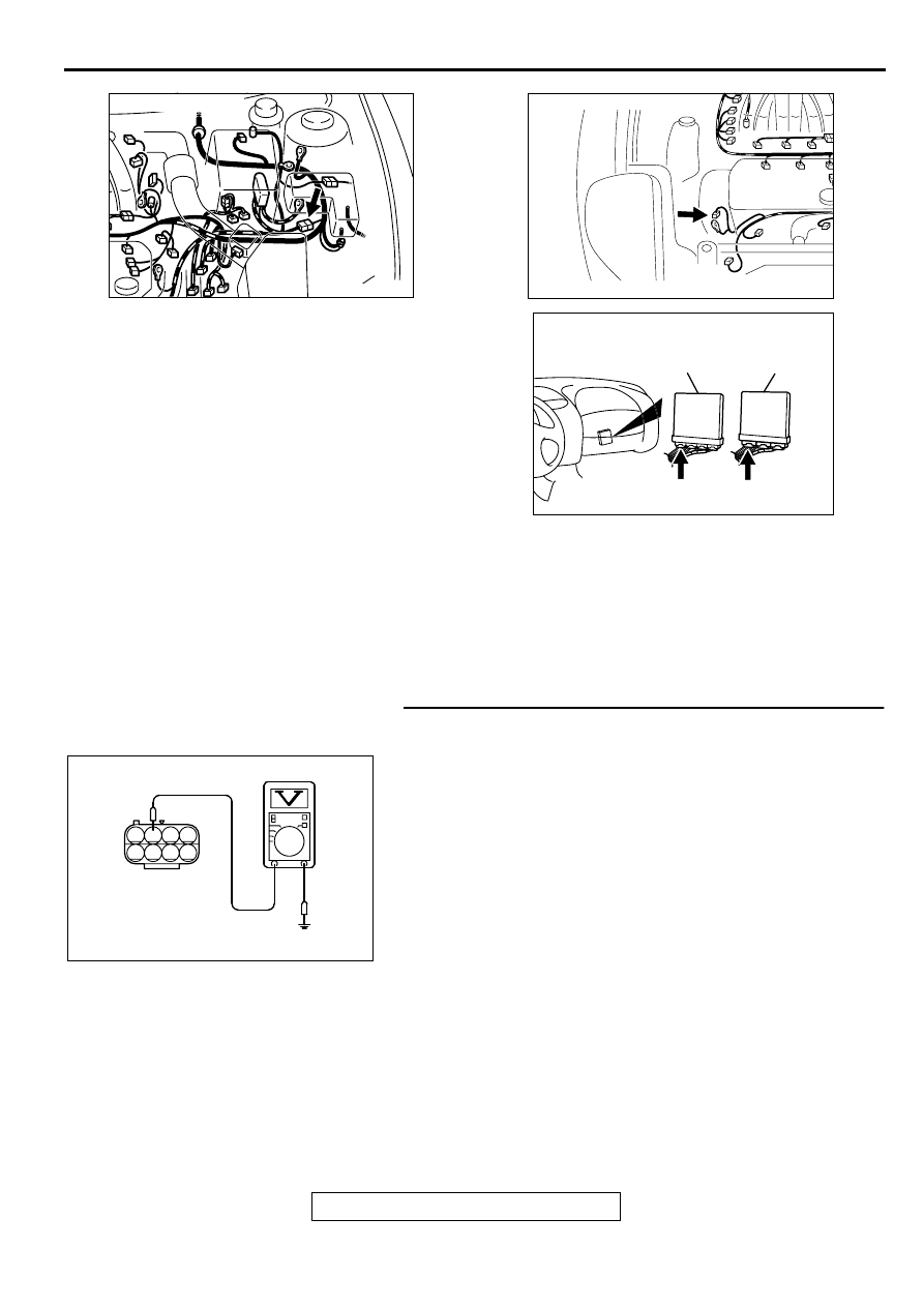
STEP 1. Check the voltage at generator intermediate 
connector B-13 by backprobing
(1) Do not disconnect the connector B-13.
(2) Start the engine and run at idle.
(3) Measure the voltage between terminal 2 and ground by 

backprobing.

a. Engine: warming up
b. Radiator fan: stopped

c. Headlight switch: OFF to ON

d. Rear defogger switch: OFF to ON
e. Stoplight switch: OFF to On

Voltage rises by 0.2-3.5 volts.

(4) Turn the ignition switch to the "LOCK" (OFF) position.

Q: Is the voltage normal?

YES : Replace the generator. Then confirm that the 

malfunction symptom is eliminated.

NO :  Go to Step 2.

AK000220

AK000220AB

CONNECTOR : B-13

AK000735AB

CONNECTOR:B-45

AK000225

CONNECTOR : C-51<M/T>, C-52<A/T>

C-52

C-51

PCM<A/T>

ECM<M/T>

AJ

AK000365 AB

B-13 CONNECTOR
HARNESS
SIDE VIEW

1 2 3 4

5 6 7 8

MULTIPORT FUEL INJECTION (MFI) DIAGNOSIS

TSB Revision

MULTIPORT FUEL INJECTION (MFI) <3.0L ENGINE>

13B-480

STEP 2. Check connector B-13 at generator intermediate 
connector for damage.
Q: Is the connector in good condition?

YES : Go to Step 3.
NO :  Repair or replace it. Refer to GROUP 00E, Harness 

Connector Inspection (

P.00E-2

). Then confirm that 

the malfunction symptom is eliminated.

STEP 3. Check connector B-45 at generator connector for 
damage.
Q: Is the connector in good condition?

YES : Go to Step 4.
NO :  Repair or replace it. Refer to GROUP 00E, Harness 

Connector Inspection (

P.00E-2

). Then confirm that 

the malfunction symptom is eliminated.

STEP 4. Check connector C-51 at ECM <M/T> or connector 
C-52 at PCM <A/T> for damage.
Q: Is the connector in good condition?

YES : Go to Step 5.
NO :  Repair or replace it. Refer to GROUP 00E, Harness 

Connector Inspection (

P.00E-2

). Then confirm that 

the malfunction symptom is eliminated.

AK000220

AK000220AB

CONNECTOR : B-13

AK000735AB

CONNECTOR:B-45

AK000225

CONNECTOR : C-51<M/T>, C-52<A/T>

C-52

C-51

PCM<A/T>

ECM<M/T>

AJ

MULTIPORT FUEL INJECTION (MFI) DIAGNOSIS

TSB Revision

MULTIPORT FUEL INJECTION (MFI) <3.0L ENGINE>

13B-481

STEP 5. Check for open circuit and short circuit to ground 
and harness damage between generator connector B-45 
terminal 1 and ECM connector C-51 terminal 8 <M/T> or 
PCM connector C-52 terminal 8 <A/T>.
Q: Is the harness wire in good condition?

YES : Replace the ECM or PCM. Then confirm that the 

malfunction symptom is eliminated.

NO :  Repair it. Then confirm that the malfunction symptom 

is eliminated.

AK000735AB

CONNECTOR:B-45

AK000225

CONNECTOR : C-51<M/T>, C-52<A/T>

C-52

C-51

PCM<A/T>

ECM<M/T>

AJ

MULTIPORT FUEL INJECTION (MFI) DIAGNOSIS

TSB Revision

MULTIPORT FUEL INJECTION (MFI) <3.0L ENGINE>

13B-482

INSPECTION PROCEDURE 27: Incorrect Idle Speed When the A/C is Operating (A/C Switch 2 Signal)

CIRCUIT OPERATION

The ECM <M/T> or PCM <A/T> increases the 
engine idle speed by driving the IAC motor when 
the automatic compressor-ECU sends a "A/C on" 
signal to the module.

The automatic compressor-ECU detects how the 
air conditioning is applying load to the engine, 
and converts the information to a voltage signal 
(High voltage= low load, Low voltage= high load). 
This voltage signal is called "A/C switch 2 signal." 

The ECM <M/T> or PCM <A/T> receives this A/C 
switch 2 signal from the automatic compressor 
controller through terminal 65 <M/T> or terminal 
61 <A/T>, and determines the idle-up speed 
according to the high or low air conditioning load.

TROUBLESHOOTING HINTS (The most likely 
causes for this code to be set are:) 

Malfunction of the A/C control system.

Open or shorted circuit, or improper connector 
contact.

ECM <M/T> or PCM <A/T> failed. 

AK000714

BL

UE-

WHITE

BL

UE-

WHITE

ENGINE CONTROL
MODULE(ECM)<M/T>
OR
POWERTRAIN CONTROL
MODULE(PCM)<A/T>

65<M/T>
61<A/T>

33

AUTOMATIC COMPRESSOR CONTROLLER

C-28

7 8

5

3 4

35

34

10 11 12

2122 23 24

13 14 15

25 26 27

16

28

17

18 19 20

29

30 31

32 33

36 37

38

9

1 2

6

65

43
50

42
49

41

48
60 61

64

46 47
58 59
67 68

45

56
66

52

51

44

53

62

54

63

57

55

 C-58<M/T>
(MU803782)

 C-55<A/T>
(MU803781)

42 43
48 49 50 51 52 53 54 55 56 57

46

45

44

58 59

60 61 62 63

64 65 66

47

41

AK000225

CONNECTOR : C-58<M/T>, C-55<A/T>

C-55

C-58

PCM<A/T>

ECM<M/T>

AI

AK000733AC

CONNECTOR:C-28


Content   ..  318  319  320  321   ..