Mitsubishi Eclipse / Eclipse Spyder (2000-2002). Service and repair manual - part 310


  Index      Mitsubishi     Mitsubishi Eclipse / Eclipse Spyder (2000-2002). Service and repair manual


Search            


Content   ..  308  309  310  311   ..


Mitsubishi Eclipse / Eclipse Spyder (2000-2002). Service and repair manual - part 310


MULTIPORT FUEL INJECTION (MFI) DIAGNOSIS

TSB Revision

MULTIPORT FUEL INJECTION (MFI) <3.0L ENGINE>

13B-439

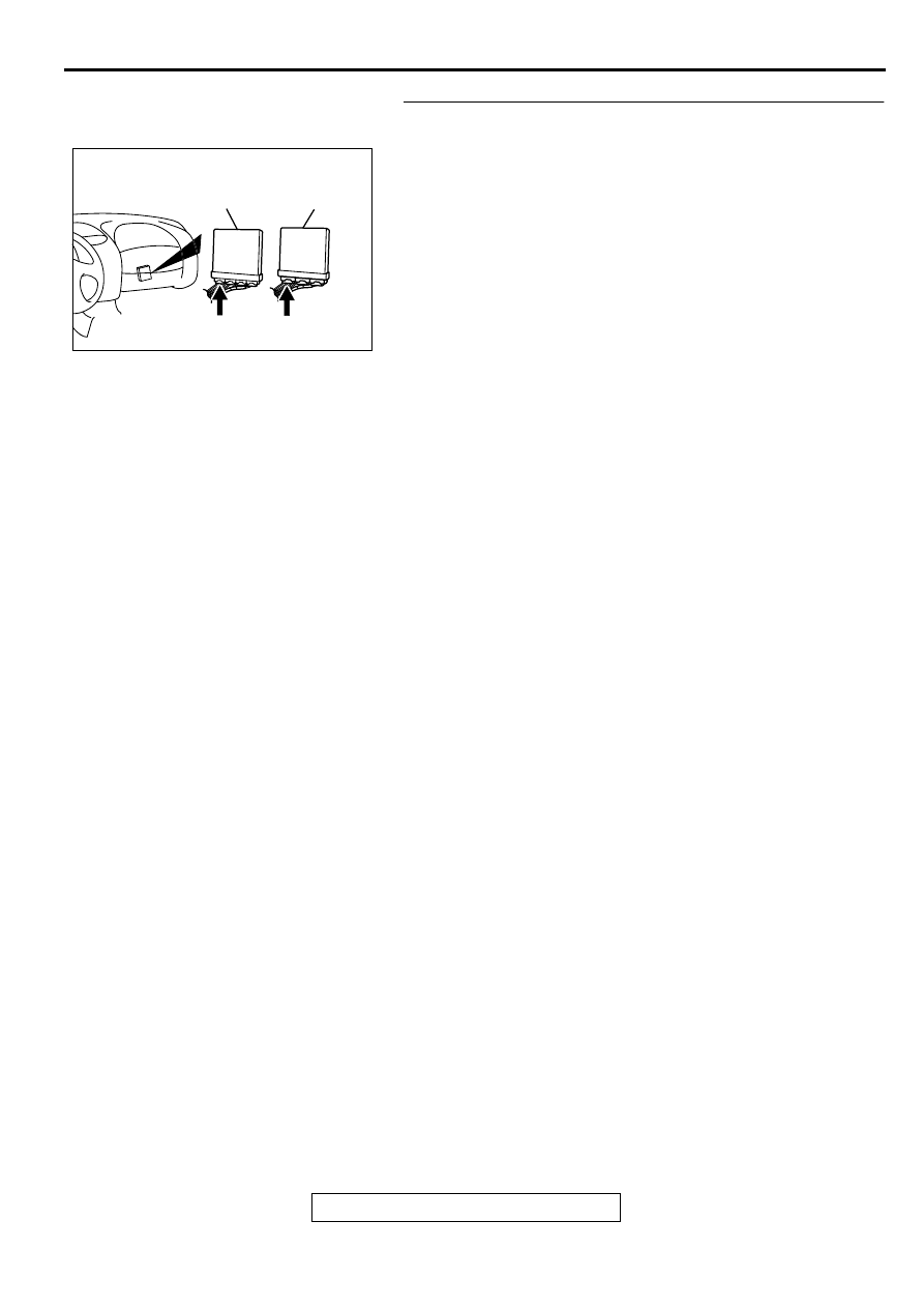
STEP 12. Check the connector C-51 at the ECM <M/T> or 
connector C-52 at the PCM <A/T> for damage.
Q: Is the connector in good condition?

YES : Go to Step 13.
NO :  Repair or replace it. Refer to GROUP 00E, Harness 

Connector Inspection (

P.00E-2

).Then confirm that the 

malfunction symptom is eliminated.

AK000225

CONNECTOR : C-51<M/T>, C-52<A/T>

C-52

C-51

PCM<A/T>

ECM<M/T>

AJ

MULTIPORT FUEL INJECTION (MFI) DIAGNOSIS

TSB Revision

MULTIPORT FUEL INJECTION (MFI) <3.0L ENGINE>

13B-440

STEP 13. Check for harness damage between injector 
connector and PCM connector.

a. Check the harness wire between injector connector B-

01 terminal 2 and ECM connector C-51 terminal 1 <M/
T> or PCM connector C-52 terminal 1 <A/T> when 
checking No.1 cylinder injector.

b. Check the harness wire between injector connector B-

02 terminal 2 and ECM connector C-51 terminal 9 <M/
T> or PCM connector C-52 terminal 9 <A/T> when 
checking No.2 cylinder injector.

c. Check the harness wire between injector connector B-

05 terminal 2 and ECM connector C-51 terminal 24 <M/
T> or PCM connector C-52 terminal 24 <A/T> when 
checking No.3 cylinder injector.

d. Check the harness wire between injector connector B-

06 terminal 2 and ECM connector C-51 terminal 2 <M/
T> or PCM connector C-52 terminal 2 <A/T> when 
checking No.4 cylinder injector.

e. Check the harness wire between injector connector B-

26 terminal 2 and ECM connector C-51 terminal 10 <M/
T> or PCM connector C-52 terminal 10 <A/T> when 
checking No.5 cylinder injector.

f. Check the harness wire between injector connector B-

25 terminal 2 and ECM connector C-51 terminal 25 <M/
T> or PCM connector C-52 terminal 25 <A/T> when 
checking No.6 cylinder injector.

Q: Is the harness wire in good condition?

YES : Check the following items, and repair or replace the 

defective items.

a. Check the ignition coil, spark plugs, spark plug 

cables.

b. Check if the injectors are clogged.

c. Check the compression pressure.

d. Check if the foreign materials (water, 

kerosene, etc.) got into fuel.

Then confirm that the malfunction symptom is 

eliminated.

NO :  Repair it. Then confirm that the malfunction symptom 

is eliminated.

INSPECTION PROCEDURE 8: Unstable Idle (Rough Idle, Hunting).

COMMENT

In cases such as the above, the cause is 
probably the air/fuel mixture or idle air control 
motor. Other systems affecting idle quality 
include the ignition system and compression.

TROUBLESHOOTING HINTS (The most likely 
causes for this case:)

Malfunction of the ignition system.

Malfunction of air/fuel ratio control system.

Malfunction of the IAC system.

Malfunction of the evaporative emission purge 
solenoid system.

Poor compression pressure.

AK000215

AK000215

B-01 B-05 B-26

B-02 B-06 B-25

AB

CONNECTORS : B-01, B-02, B-05, B-06,
                            B-25, B-26

AK000225

CONNECTOR : C-51<M/T>, C-52<A/T>

C-52

C-51

PCM<A/T>

ECM<M/T>

AJ

MULTIPORT FUEL INJECTION (MFI) DIAGNOSIS

TSB Revision

MULTIPORT FUEL INJECTION (MFI) <3.0L ENGINE>

13B-441

Vacuum leak.

Malfunction of the EGR solenoid system.

DIAGNOSIS

Required Special Tool:
MB991502: Scan Tool (MUT-II)

STEP 1. Check if the battery terminal is disconnected

Q: Has the battery terminal been disconnected lately?

YES : Start the engine and let it run at idle for approximate 

10 minutes after engine warm up. Then, if a 
malfunction occurs, go to Step 2.

NO :  Go to Step 2.

STEP 2. Using scan tool MB991502, read the diagnostic 
trouble code (DTC).

CAUTION

To prevent damage to scan tool MB991502, always turn the 
ignition switch is to the "LOCK" (OFF) position before 
connecting or disconnecting scan tool MB991502.
(1) Connect scan tool MB991502 to the data link connector.
(2) Turn the ignition switch to the "ON" position.
(3) Read the DTC.
(4) Turn the ignition switch to the "LOCK" (OFF) position.

Q: Is the DTC is output?

YES : Refer to, Diagnostic Trouble Code Chart (

P.13B-18

).

NO :  Go to Step 3.

STEP 3. Check the engine idling state.

Q: Is it hunting remarkably?

YES : Go to Step 4.
NO :  Go to Step 5.

STEP 4. Check the following items.
(1) Carry out the following cleaning.

a. Clean the throttle valve area (

P.13B-551

).

(2) After cleaning, confirm that the malfunction symptom is 

eliminated.

Q: Is the malfunction symptom resolved?

YES : The check is completed.
NO :  Check the following items, and repair or replace the 

defective items.

a. Broken intake manifold gasket.
b. Broken air intake hose.

c. Broken vacuum hose.

d. Positive crankcase ventilation valve does not 

operate.

Then confirm that the malfunction symptom is 

eliminated.

AKX01177

16 PIN

MB991502

AB

MULTIPORT FUEL INJECTION (MFI) DIAGNOSIS

TSB Revision

MULTIPORT FUEL INJECTION (MFI) <3.0L ENGINE>

13B-442

STEP 5. Check the idle air control (IAC) motor operation 
sound.
(1) Check that the engine coolant temperature is 20

°

 C (68

°

 F) 

or below.

NOTE: Disconnecting the engine coolant temperature 
sensor connector and connecting the harness side of the 
connector to another engine coolant temperature sensor 
that is at 20

° 

C (68

°

 F) or below is also okay.

(2) Check the operation sound of the IAC motor can be heard 

after the ignition is switched to the "ON" position (but 
without starting the engine).

An operation sound is heard.

(3) Turn the ignition switch to the "LOCK" (OFF) position.

Q: Did you hear the operation sound?

YES : Go to Step 6.
NO :  Refer to, DTC P0506 

 Idle Control System RPM 

Lower Than Expected (

P.13B-359

), DTC P0507 

 Idle 

Control System RPM Higher Than Expected (

P.13B-

368

).

STEP 6. Using scan tool MB991502, check actuator test 
items 01, 02, 03, 04, 05, 06: Injector.

CAUTION

To prevent damage to scan tool MB991502, always turn the 
ignition switch to the "LOCK" (OFF) position before 
connecting or disconnecting scan tool MB991502.
(1) Connect scan tool MB991502 to the data link connector.
(2) Turn the ignition switch to the "ON" position.
(3) Check following items in the actuator test. Refer to, Actuator 

Test Reference Table (

P.13B-529

).

a. Item 01, 02, 03, 04, 05, 06: Injector.

(4) Turn the ignition switch to the "LOCK" (OFF) position.

Q: Is the actuator operating properly?

YES : Go to Step 7.
NO :  Refer to, DTC P0201,P0203,P0205 

 Injector Circuit 

Malfunction (

P.13B-219

), DTC P0202, P0204, P0206 

  Injector Circuit Malfunction (

P.13B-227

)

ACX02523AI

IDLE AIR
CONTROL
MOTOR

CONNECTOR:B-34

AKX01177

16 PIN

MB991502

AB


Content   ..  308  309  310  311   ..