Mitsubishi Eclipse / Eclipse Spyder (2000-2002). Service and repair manual - part 258


  Index      Mitsubishi     Mitsubishi Eclipse / Eclipse Spyder (2000-2002). Service and repair manual


Search            


Content   ..  256  257  258  259   ..


Mitsubishi Eclipse / Eclipse Spyder (2000-2002). Service and repair manual - part 258


MULTIPORT FUEL INJECTION (MFI) DIAGNOSIS

TSB Revision

MULTIPORT FUEL INJECTION (MFI) <3.0L ENGINE>

13B-231

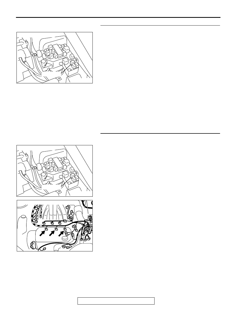
STEP 5. Check connector A-21X at MFI relay for damage.
Q: Is the connector in good condition?

YES : Repair harness wire between MFI relay connector 

and injector connector because of open circuit or 
short circuit to ground.

a. Repair harness wire between MFI relay 

connector A-21X terminal 1 and injector 
connector B-02 terminal 1 when checking No.2 
cylinder.

b. Repair harness wire between MFI relay 

connector A-21X terminal 1 and injector 
connector B-06 terminal 1 when checking No.4 
cylinder.

c. Repair harness wire between MFI relay 

connector A-21X terminal 1 and injector 
connector B-25 terminal 1 when checking No.6 
cylinder.

Then go to Step 10.

NO :  Repair or replace it. Refer to GROUP 00E, Harness 

Connector Inspection (

P.00E-2

). Then go to Step 10.

STEP 6. Check for harness damage between MFI relay 
connector and injector connector.

a. Check the harness wire between MFI relay connector A-

21X terminal 1 and injector connector B-02 terminal 1 when 
checking No.2 cylinder.

b. Check the harness wire between MFI relay connector A-

21X terminal 1 and injector connector B-06 terminal 1 when 
checking No.4 cylinder.

c. Check the harness wire between MFI relay connector A-

21X terminal 1 and injector connector B-25 terminal 1 when 
checking No.6 cylinder.

Q: Is the harness wire in good condition?

YES : Go to Step 7.
NO :  Repair it. Then go to Step 10.

AK000226

AK000226AB

CONNECTOR : A-21X

MFI RELAY

AK000226

AK000226AB

CONNECTOR : A-21X

MFI RELAY

AK000213AB

CONNECTORS : B-02, B-06, B-25

B-02 B-06 B-25

MULTIPORT FUEL INJECTION (MFI) DIAGNOSIS

TSB Revision

MULTIPORT FUEL INJECTION (MFI) <3.0L ENGINE>

13B-232

STEP 7. Check connector C-51 at ECM <M/T> or connector 
C-52 at PCM <A/T> for damage.
Q: Is the connector in good condition?

YES : Go to Step 8.
NO :  Repair or replace it. Refer to GROUP 00E, Harness 

Connector Inspection (

P.00E-2

). Then go to Step 10.

STEP 8. Check for open circuit and short circuit to ground 
and harness damage between injector connector and ECM 
connector <M/T> or PCM connector <A/T>.

a. Check the harness wire between injector connector B-02 

terminal 2 and ECM connector C-51 terminal 9 <M/T> or 
PCM connector C-52 terminal 9 <A/T> when checking No.2 
cylinder.

b. Check the harness wire between injector connector B-06 

terminal 2 and ECM connector C-51 terminal 2 <M/T> or 
PCM connector C-52 terminal 2 <A/T> when checking No.4 
cylinder.

c. Check the harness wire between injector connector B-25 

terminal 2 and ECM connector C-51 terminal 25 <M/T> or 
PCM connector C-52 terminal 25 <A/T> when checking 
No.6 cylinder.

Q: Is the harness wire in good condition?

YES : Go to Step 9.
NO :  Repair it. Then go to Step 10.

AK000225

CONNECTOR : C-51<M/T>, C-52<A/T>

C-52

C-51

PCM<A/T>

ECM<M/T>

AJ

AK000213AB

CONNECTORS : B-02, B-06, B-25

B-02 B-06 B-25

AK000225

CONNECTOR : C-51<M/T>, C-52<A/T>

C-52

C-51

PCM<A/T>

ECM<M/T>

AJ

MULTIPORT FUEL INJECTION (MFI) DIAGNOSIS

TSB Revision

MULTIPORT FUEL INJECTION (MFI) <3.0L ENGINE>

13B-233

STEP 9. Using the oscilloscope, check the injector.
(1) Disconnect the injector connector B-02 <No.2 cylinder> or 

B-06 <No.4 cylinder> or B-25 <No.6 cylinder> and connect 
the test harness special tool (MB991348) in between. (All 
terminals should be connected)

(2) Connect the oscilloscope probe to the injector side 

connector terminal 2.

NOTE: When measuring with the ECM or PCM side 
connector, connect an oscilloscope probe to the each of the 
following terminals.

.

ECM or PCM terminal 9 when checking No.2 cylinder.

ECM or PCM terminal 2 when checking No.4 cylinder.

ECM or PCM terminal 25 when checking No.6 cylinder.

(3) Start the engine and run at idle.
(4) Measure the waveform.

The waveform should show a normal pattern similar to 
the illustration.

(5) Turn the ignition switch to the "LOCK" (OFF) position.

Q: Is the waveform normal?

YES : It can be assumed that this malfunction is intermittent. 

Refer to GROUP 00, How to Use Troubleshooting/
Inspection Service Points (

P.00-6

).

NO :  Replace the ECM or PCM. Then go to Step 10.

STEP 10. Test the OBD-II drive cycle.
(1) Carry out a test drive with the drive cycle pattern. Refer to, 

Procedure 6 

 Other Monitor (

P.13B-4

).

(2) Check the diagnostic trouble code (DTC).

Q: Is the DTC P0202, P0204, P0206 is output?

YES : Retry the troubleshooting.
NO :  The inspection is complete.

DTC P0300: Random Misfire Detected

Random Misfire Circuit

Refer to, DTC P0201, P0203, P0205 

  Injector 

Circuit (

P.13B-219

).

Refer to, DTC P0202, P0204, P0206 

  Injector 

Circuit (

P.13B-227

).

CIRCUIT OPERATION

Refer to, DTC P0201, P0203, P0205 

  Injector 

Circuit (

P.13B-219

).

Refer to, DTC P0202, P0204, P0206 

  Injector 

Circuit (

P.13B-227

).

TECHNICAL DESCRIPTION

If a misfire occurs while the engine is running, the 
engine speed changes for an instant.

The ECM <M/T> or PCM <A/T> checks for such 
changes in engine speed.

DTC SET CONDITIONS

Check Conditions

Five seconds or more have passed after the 
engine was started.

Engine speed is between 440 and 6,000 r/min.

Engine coolant temperature is higher than -10

° 

(14

° 

F).

Intake air temperature is higher than -10

° 

C (14

° 

F).

Barometric pressure is higher than 76 kPa (11 
psi).

Adaptive learning is complete for the vane which 

generates a crankshaft position signal.

AK000587

OSCILLOSCOPE

OSCILLO

SCOPE

PROBE

1

2

AB

INJECTOR
CONNECTOR

AKX01557 AB

A

NORMAL  WAVEFORM

A:INJECTOR DRIVE TIME

MULTIPORT FUEL INJECTION (MFI) DIAGNOSIS

TSB Revision

MULTIPORT FUEL INJECTION (MFI) <3.0L ENGINE>

13B-234

While the engine is running, excluding gear 
shifting, deceleration, sudden acceleration/
deceleration and A/C compressor switching.

Vehicle speed is 2.5km (1.6mph) or more.

The throttle deviation is -0.059v/10ms to +0.059v/
10ms.

Judgement Criteria (change in the angular 

acceleration of the crankshaft is used for 
misfire detection).

Misfire has occurred in 4 or more of the last 200 
revolutions [when the catalyst temperature is 
higher than 950

°

 C (1742

° 

F)].

or

Misfire has occurred in 20 or more of the last 
1,000 revolutions (corresponding to 1.5 times the 
limit of emission standard).

TROUBLESHOOTING HINTS (The most likely 
causes for this code to be set are:)

Ignition system related part(s) failed.

Poor crankshaft position sensor.

Incorrect air/fuel ratio.

Low compression pressure.

Skipping of timing belt teeth.

EGR system and EGR valve failed.

ECM failed. <M/T>

PCM failed. <A/T>

DIAGNOSIS

Required Special Tools
MB991502: Scan Tool (MUT-II)

STEP 1. Using scan tool MB991502, check data list item 22: 
Crankshaft Position Sensor.

CAUTION

To prevent damage to scan tool MB991502, always turn the 
ignition switch to the "LOCK" (OFF) position before 
connecting or disconnecting scan tool MB991502.
(1) Connect scan tool MB991502 to the data link connector.
(2) Start the engine and run at idle.
(3) Set scan tool MB991502 to the data reading mode for item 

22, Crankshaft Position Sensor.

(4) Check the waveform of the crankshaft position sensor while 

keeping the engine speed constant.

The pulse width should be constant.

(5) Turn the ignition switch to "LOCK" (OFF) position.

Q: Is the sensor operating properly?

YES : Go to Step 2.
NO :  Refer to, DTC P0335 

 Crankshaft Position Sensor 

Circuit Malfunction (

P.13B-248

).

AKX01177

16 PIN

MB991502

AB


Content   ..  256  257  258  259   ..