Mitsubishi Eclipse / Eclipse Spyder (2000-2002). Service and repair manual - part 181


  Index      Mitsubishi     Mitsubishi Eclipse / Eclipse Spyder (2000-2002). Service and repair manual


Search            


Content   ..  179  180  181  182   ..


Mitsubishi Eclipse / Eclipse Spyder (2000-2002). Service and repair manual - part 181


MULTIPORT FUEL INJECTION (MFI) DIAGNOSIS

TSB Revision

MULTIPORT FUEL INJECTION (MFI) <2.4L ENGINE>

13A-423

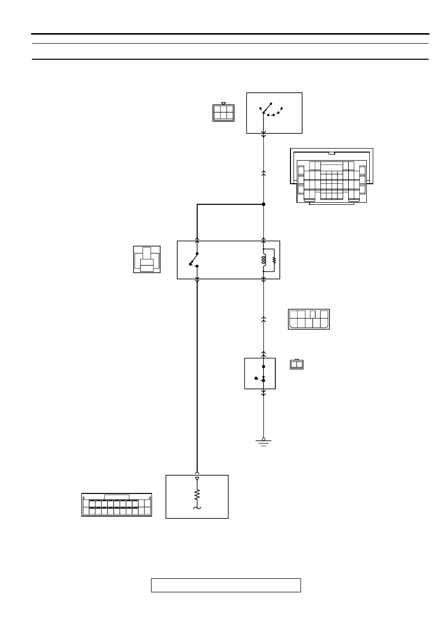
INSPECTION PROCEDURE 31: Ignition Switch-ST System. <M/T>

AK000681

4 5 6

1 2 3

BL

ACK

-

RED

BL

ACK

-

RED

BL

ACK

-

RED

3

4

5

1

2

8

7

2

6

3

5

1

BL

ACK

-RED

4

BL

ACK

GREEN-

BL

ACK

GREEN-

BL

ACK

BL

ACK

-

RED

LOCK

ACC

C-87

R

IGNITION
SWITCH

IG2

IG1

ST

16

5

A-18X

4

2

3

1

STARTER
RELAY

71

4

2

INTERLOCK
SWITCH

C-02

1

OFF

ON

ENGINE
CONTROL
MODULE(ECM)

C-28

7 8

5

3 4

35

34

10 11 12

2122 23 24

13 14 15

25 26 27

16

28

17

18 19 20

29

30 31

32 33

36 37

38

9

1 2

6

       C-60
(MU803772)

      C-07
MU801333

82

78

81

80

89 90 91 92

79

87

71

74

73

72

76

75

77

85

88

83 84

86

1 2

MULTIPORT FUEL INJECTION (MFI) DIAGNOSIS

TSB Revision

MULTIPORT FUEL INJECTION (MFI) <2.4L ENGINE>

13A-424

CIRCUIT OPERATION

The battery positive voltage is supplied to the 
ECM (terminal 71) via the starter relay during 
engine cranking. With this, the ECM detects that 
the engine is being cranked.

TROUBLESHOOTING HINTS (The most likely 
causes for this case:)

Malfunction of the ignition switch.

Malfunction of the starter relay.

Improper connector contact, open circuit or short-
circuited harness wire.

Malfunction of the ECM.

AK000356

CONNECTOR : A-18X

AB

AK000733AC

CONNECTOR:C-28

AK000280

CONNECTOR:C-60

BI

AK000312AJ

CONNECTOR:C-07

AK000219

CONNECTOR:C-87

AC

AK000312AF

CONNECTOR : C-02

MULTIPORT FUEL INJECTION (MFI) DIAGNOSIS

TSB Revision

MULTIPORT FUEL INJECTION (MFI) <2.4L ENGINE>

13A-425

DIAGNOSIS

STEP 1. Check connector A-18X at starter relay for 
damage.
Q: Is the connector in good condition?

YES : Go to Step 2.
NO :  Repair or replace it. Refer to GROUP 00E, Harness 

Connector Inspection (

P.00E-2

).Then confirm that the 

malfunction symptom is eliminated.

STEP 2. Check the starter relay.
Refer to GROUP 16, Starting system 

 On-vehicle Service 


Starter relay check.

Q: Are there any abnormalities?

YES : Go to Step 3.
NO :  Repair or replace it. Then confirm that the malfunction 

symptom is eliminated.

STEP 3. Check the power supply voltage at starter relay 
connector A-18X.
(1) Disconnect the connector A-18X and measure at the 

harness side.

(2) Turn the ignition switch to the "START" position.
(3) Measure the voltage between terminal 3, 4 and ground.

Voltage should be battery positive voltage.

(4) Turn the ignition switch to the "LOCK" (OFF) position.

Q: Is the voltage normal?

YES : Go to Step 4.
NO :  Check connector C-28 at intermediate connector for 

damage, and repair or replace as required. Refer to 
GROUP 00E, Harness Connector Inspection (

P.00E-

2

). If intermediate connector is in good condition, 

repair harness wire between ignition switch connector 
C-87 terminal 5 and starter relay connector A-18X 
terminal 3,4 because of open circuit. Then confirm 
that the malfunction symptom is eliminated.

AK000356

CONNECTOR : A-18X

AB

AK000382AB

A-18X HARNESS
SIDE CONNECTOR

1

2

4

3

5

MULTIPORT FUEL INJECTION (MFI) DIAGNOSIS

TSB Revision

MULTIPORT FUEL INJECTION (MFI) <2.4L ENGINE>

13A-426

STEP 4. Check connector C-620 at ECM for damage.
Q: Is the connector in good condition?

YES : Go to Step 5.
NO :  Repair or replace it. Refer to GROUP 00E, Harness 

Connector Inspection (

P.00E-2

). Then confirm that 

the malfunction symptom is eliminated.

STEP 5. Check the power supply voltage at ECM connector 
C-60.
(1) Disconnect the connector C-60 and measure at the harness 

side.

(2) Turn the ignition switch to the "START" position.
(3) Measure the voltage between terminal 71 and ground.

Voltage should be battery positive voltage.

(4) Turn the ignition switch to the "LOCK" (OFF) position.

Q: Is the voltage normal?

YES : Go to Step 6.
NO :  Repair harness wire between starter relay connector 

A-18X terminal 2 and ECM connector C-60 terminal 
71 because of open circuit. Then confirm that the 
malfunction symptom is eliminated.

STEP 6. Check connector C-02 at interlock switch for 
damage.
Q: Is the connector in good condition?

YES : Go to Step 7.
NO :  Repair or replace it. Refer to GROUP 00E, Harness 

Connector Inspection (

P.00E-2

). Then confirm that 

the malfunction symptom is eliminated.

STEP 7. Check the interlock switch.
Refer to GROUP 21A, On-vehicle Service 

 Interlock switch 

check and adjustment (

P.21A-9

)

Q: Are there any abnormalities?

YES : Go to Step 8.
NO :  Repair or replace it. Then confirm that the malfunction 

symptom is eliminated.

AK000280

CONNECTOR:C-60

BI

AK000410 AC

71

72

73

74

75

76

77

78

79

80

81

82

83

84

85

86

87

88

89

90

91

92

C-60 HARNESS
SIDE CONNECTOR

AK000312AF

CONNECTOR : C-02


Content   ..  179  180  181  182   ..