Mitsubishi Eclipse / Eclipse Spyder (2000-2002). Service and repair manual - part 122


  Index      Mitsubishi     Mitsubishi Eclipse / Eclipse Spyder (2000-2002). Service and repair manual


Search            


Content   ..  120  121  122  123   ..


Mitsubishi Eclipse / Eclipse Spyder (2000-2002). Service and repair manual - part 122


MULTIPORT FUEL INJECTION (MFI) DIAGNOSIS

TSB Revision

MULTIPORT FUEL INJECTION (MFI) <2.4L ENGINE>

13A-187

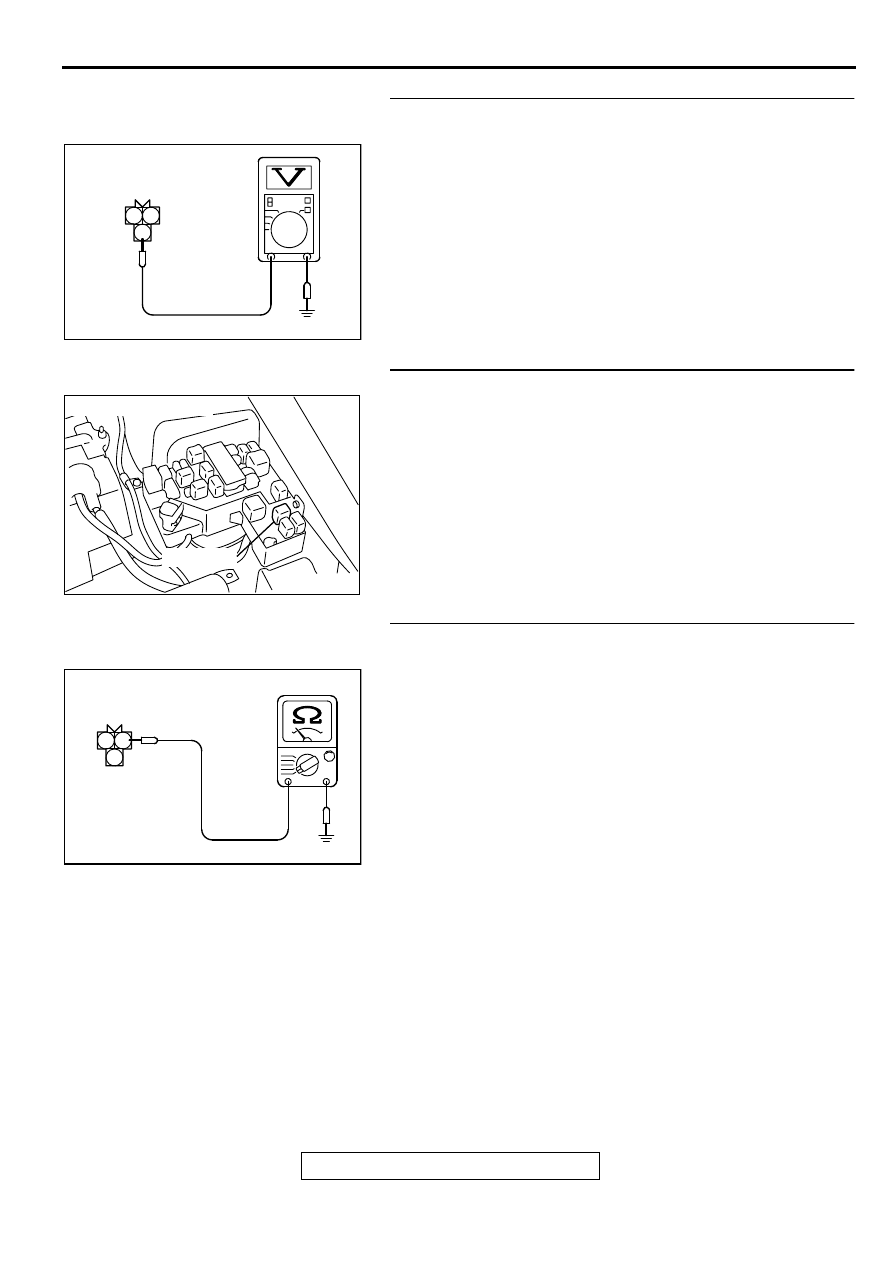
STEP 11. Check the power supply voltage at crankshaft 
position sensor harness side connector B-20.
(1) Disconnect the connector B-20 and measure at the harness 

side.

(2) Turn the ignition switch to the "ON" position.
(3) Measure the voltage between terminal 3 and ground.

Voltage should be battery positive voltage.

(4) Turn the ignition switch to the "LOCK" (OFF) position.

Q: Is the voltage normal?

YES : Go to Step 13.
NO :  Go to Step 12.

STEP 12. Check connector A-21X at MFI relay for damage.
Q: Is the connector in good condition?

YES : Repair harness wire between MFI relay connector A-

21X terminal 1 and crankshaft position sensor 
connector B-20 terminal 3 because of open circuit or 
short circuit to ground. Then go to Step 20.

NO :  Repair or replace it. Refer to GROUP 00E, Harness 

Connector Inspection (

P.00E-2

). Then go to Step 20.

STEP 13. Check the continuity at crankshaft position 
sensor harness side connector B-20.
(1) Disconnect the connector B-20 and measure at the harness 

side.

(2) Check for the continuity between terminal 1 and ground.

Should be less than 2 ohm.

Q: Is the continuity normal?

YES : Go to Step 14.
NO :  Repair harness wire between crankshaft position 

sensor connector B-20 terminal 1 and ground 
because of open circuit or harness damage. Then go 
to Step 20.

AKX01417AC

2 1

3

B-20 HARNESS
SIDE CONNECTOR

AK000226

AK000226AB

CONNECTOR : A-21X

MFI RELAY

AKX01418 AC

2 1

3

B-20 HARNESS
SIDE CONNECTOR

MULTIPORT FUEL INJECTION (MFI) DIAGNOSIS

TSB Revision

MULTIPORT FUEL INJECTION (MFI) <2.4L ENGINE>

13A-188

STEP 14. Check connector A-21X at the MFI relay for 
damage.
Q: Is the harness connector in good condition?

YES : Go to Step 15.
NO :  Repair or replace it. Refer to GROUP 00E, Harness 

Connector Inspection (

P.00E-2

). Then go to Step 20.

STEP 15. Check connector C-60 at ECM <M/T> or 
connector C-54 at PCM <A/T> for damage.
Q: Is the connector in good condition?

YES : Go to Step 16.
NO :  Repair or replace it. Refer to GROUP 00E, Harness 

Connector Inspection (

P.00E-2

). Then go to Step 20.

STEP 16. Check for harness damage between MFI relay 
connector A-21X terminal 1 and crankshaft position 
sensor connector B-20 terminal 3.
Q: Is the harness wire in good condition?

YES : Go to Step 17.
NO :  Repair it. Then go to Step 20.

AK000226

AK000226AB

CONNECTOR : A-21X

MFI RELAY

AK000280

C-54

C-60

ECM<M/T>
OR
PCM<A/T>

CONNECTORS:C-60<M/T>,C-54<A/T>

BB

AK000226

AK000226AB

CONNECTOR : A-21X

MFI RELAY

AK000546AB

CONNECTOR:C-20

MULTIPORT FUEL INJECTION (MFI) DIAGNOSIS

TSB Revision

MULTIPORT FUEL INJECTION (MFI) <2.4L ENGINE>

13A-189

STEP 17. Check for harness damage between crankshaft 
position sensor connector B-20 terminal 2 and ECM 
connector C-60 terminal 89 <M/T> or PCM connector C-54 
terminal 45 <A/T>.
Q: Is the harness wire in good condition?

YES : Go to Step 18.
NO :  Repair it. Then go to Step 20.

STEP 18. Check for harness damage between crankshaft 
position sensor connector B-20 terminal 1 and ground.
Q: Is the harness wire in good condition?

YES : Go to Step 19.
NO :  Repair it. Then go to Step 20.

STEP 19. Check the crankshaft position sensor vane.

Q: Is the vane in a good condition?

YES : Replace the crankshaft position sensor. Then go to 

Step 20.

NO :  Repair it. Then go to Step 20.

AK000546AB

CONNECTOR:C-20

AK000280

C-54

C-60

ECM<M/T>
OR
PCM<A/T>

CONNECTORS:C-60<M/T>,C-54<A/T>

BB

AK000546AB

CONNECTOR:C-20

MULTIPORT FUEL INJECTION (MFI) DIAGNOSIS

TSB Revision

MULTIPORT FUEL INJECTION (MFI) <2.4L ENGINE>

13A-190

STEP 20. Test the OBD-II drive cycle.
(1) Carry out a test drive with the drive cycle pattern. Refer to, 

Procedure 6 

 Other Monitor (

P.13A-5

).

(2) Check the diagnostic trouble code (DTC).

Q: Is the DTC P0335 is output?

YES : Retry the troubleshooting.
NO :  The inspection is complete.


Content   ..  120  121  122  123   ..