Mitsubishi Eclipse / Eclipse Spyder (2000-2002). Service and repair manual - part 119


  Index      Mitsubishi     Mitsubishi Eclipse / Eclipse Spyder (2000-2002). Service and repair manual


Search            


Content   ..  117  118  119  120   ..


Mitsubishi Eclipse / Eclipse Spyder (2000-2002). Service and repair manual - part 119


MULTIPORT FUEL INJECTION (MFI) DIAGNOSIS

TSB Revision

MULTIPORT FUEL INJECTION (MFI) <2.4L ENGINE>

13A-175

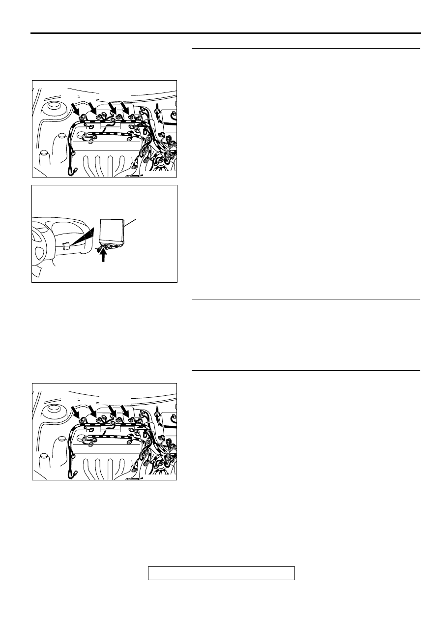
STEP 6. Check for harness damage between injector 
connector and ECM connector <M/T> or PCM connector 
<A/T>.

a. Check the harness wire between injector connector B-01 

terminal 2 and ECM connector C-49 terminal 1 <M/T> or 
PCM connector C-50 terminal 1 <A/T> when checking No.1 
cylinder.

b. Check the harness wire between injector connector B-02 

terminal 2 and ECM connector C-49 terminal 14 <M/T> or 
PCM connector C-50 terminal 9 <A/T> when checking No.2 
cylinder.

c. Check the harness wire between injector connector B-05 

terminal 2 and ECM connector C-49 terminal 2 <M/T> or 
PCM connector C-50 terminal 24 <A/T> when checking 
No.3 cylinder.

d. Check the harness wire between injector connector B-06 

terminal 2 and ECM connector C-49 terminal 15 <M/T> or 
PCM connector C-50 terminal 2 <A/T> when checking No.4 
cylinder.

Q: Is the harness wire in good condition?

YES : Go to Step 7.
NO :  Repair it. Then go to Step 9.

STEP 7. Check the compression.
Refer to GROUP 11A, On-Vehicle Service-Compression 
Pressure Check (

P.11A-8

).

Q: Are there any abnormalities?

YES : Go to Step 8.
NO :  Repair or replace it. Then go to Step 9.

STEP 8. Replace the injector.
(1) Replace the injector.
(2) Carry out a test drive with the drive cycle pattern. Refer to, 

Procedure 6 

 Other Monitor (

P.13A-5

).

(3) Check the diagnostic trouble code (DTC).

Q: Is the DTC P0301, P0302, P0303, P0304 is output?

YES : Replace the ECM or PCM. Then go to Step 9.
NO :  The inspection is complete.

AK000273AB

AK000273

CONNECTOR : B-01, B-02, B-05, B-06 

B-01 B-02 B-05 B-06

AK000280

C-49,C-50

ECM<M/T>
OR
PCM<A/T>

CONNECTORS:C-49<M/T>,C-50<A/T>

BC

AK000273AB

AK000273

CONNECTOR : B-01, B-02, B-05, B-06 

B-01 B-02 B-05 B-06

MULTIPORT FUEL INJECTION (MFI) DIAGNOSIS

TSB Revision

MULTIPORT FUEL INJECTION (MFI) <2.4L ENGINE>

13A-176

STEP 9. Test the OBD-II drive cycle.
(1) Carry out a test drive with the drive cycle pattern. Refer to, 

Procedure 6 

 Other Monitor (

P.13A-5

).

(2) Check the diagnostic trouble code (DTC).

Q: Is the DTC P0301, P0302, P0303, P0304 is output?

YES : Retry the troubleshooting.
NO :  The inspection is complete.

DTC P0325: Knock Sensor 1 Circuit Malfunction

AK000662

2

1

WHITE

BLA

CK

BLA

CK

BLA

CK

 C-60<M/T>
(MU803772)

78<M/T>
90<A/T>

KNOCK SENSOR

2

1

     B-35
MU802661

82

78

81

80

89 90 91 92

79

87

71

74

73

72

76

75

77

85

88

83 84

86

98

78

71

88 89

76 77

72
79
91

73
80

74

75

81
92

8283
93

8485

94

8687

9596

90

97

 C-57<A/T>
(MU803782)

ENGINE CONTROL
MODULE(ECM)<M/T>
OR
POWERTRAIN CONTROL
MODULE(PCM)<A/T>

MULTIPORT FUEL INJECTION (MFI) DIAGNOSIS

TSB Revision

MULTIPORT FUEL INJECTION (MFI) <2.4L ENGINE>

13A-177

CIRCUIT OPERATION

The knock sensor sends a signal voltage to the 
ECM (terminal 78) <M/T> or PCM (terminal 90) 
<A/T>.

TECHNICAL DESCRIPTION

The knock sensor converts the vibration of the 
cylinder block into a voltage and outputs it. If 
there is a malfunction of the knock sensor, the 
voltage output will not change.

The ECM <M/T> or PCM <A/T> checks whether 
the voltage output changes.

DTC SET CONDITIONS

Check Conditions

Ignition switch: ON

60 seconds or more have passed after the 
ignition switch was turned on or the starting 
sequence was completed.

Engine speed is higher than 2,500 r/min.

Judgment Criteria

Knock sensor output voltage (knock sensor peak 
voltage in each 1/2 turn of the crankshaft) has not 
changed more than 0.06 V in the last consecutive 
200 periods.

TROUBLESHOOTING HINTS (The most likely 
causes for this code to be set are:)

Knock sensor failed.

Open or shorted knock sensor circuit, or loose 
connector.

ECM <M/T> failed.

PCM <A/T> failed.

DIAGNOSIS

Required Special Tools
MB991502: Scan Tool (MUT-II)

STEP 1 Check connector B-35 at the knock sensor for 
damage.
Q: Is the connector in good condition?

YES : Go to Step 2.
NO :  Repair or replace it. Refer to GROUP 00E, Harness 

Connector Inspection (

P.00E-2

). Then go to Step 6.

ACX02470

KNOCK SENSOR

CONNECTOR:B-35

AE

AK000280

C-60

ECM<M/T>
OR
PCM<A/T>

CONNECTORS:C-60<M/T>,C-57<A/T>

BE

C-57

ACX02470

KNOCK SENSOR

CONNECTOR:B-35

AE

MULTIPORT FUEL INJECTION (MFI) DIAGNOSIS

TSB Revision

MULTIPORT FUEL INJECTION (MFI) <2.4L ENGINE>

13A-178

STEP 2 Check the continuity at knock sensor harness side 
connector B-35.
(1) Disconnect the connector B-35 and measure at the harness 

side.

(2) Check for the continuity between terminal 2 and ground.

Should be less than 2 ohm.

Q: Is the continuity normal?

YES : Go to Step 3.
NO :  Repair harness wire between knock sensor connector 

B-35 terminal 2 and ground because of open circuit or 
harness damage. Then go to Step 6.

STEP 3. Check connector C-60 at ECM <M/T> or connector 
C-57 at PCM <A/T> for damage.
Q: Is the connector in good condition?

YES : Go to Step 4.
NO :  Repair or replace it. Refer to GROUP 00E, Harness 

Connector Inspection (

P.00E-2

). Then go to Step 6.

AKX01415

1

2

B-35 HARNESS
SIDE CONNECTOR

AE

AK000280

C-60

ECM<M/T>
OR
PCM<A/T>

CONNECTORS:C-60<M/T>,C-57<A/T>

BE

C-57


Content   ..  117  118  119  120   ..