Mitsubishi Eclipse / Eclipse Spyder (2000-2002). Service and repair manual - part 103


  Index      Mitsubishi     Mitsubishi Eclipse / Eclipse Spyder (2000-2002). Service and repair manual


Search            


Content   ..  101  102  103  104   ..


Mitsubishi Eclipse / Eclipse Spyder (2000-2002). Service and repair manual - part 103


MULTIPORT FUEL INJECTION (MFI) DIAGNOSIS

TSB Revision

MULTIPORT FUEL INJECTION (MFI) <2.4L ENGINE>

13A-111

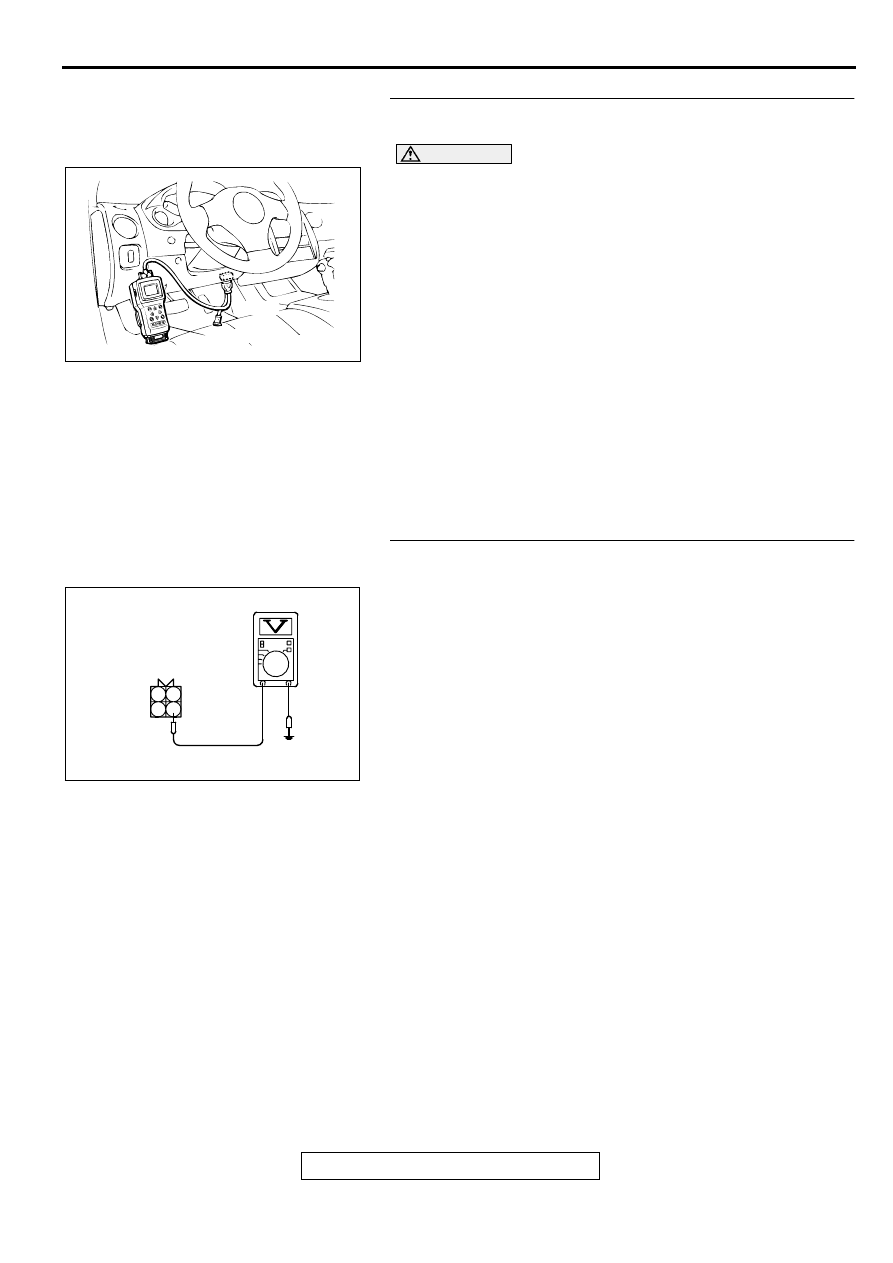
STEP 1. Using scan tool MB991502, check data list item 11: 
Heated Oxygen Sensor (front).

CAUTION

To prevent damage to scan tool MB991502, always turn the 
ignition switch to the "LOCK" (OFF) position before 
connecting or disconnecting scan tool MB991502.
(1) Connect scan tool MB991502 to the data link connector.
(2) Start the engine and run at idle.
(3) Set scan tool MB991502 to the data reading mode for item 

11, Heated Oxygen Sensor (front).

Warming up the engine. When the engine is revved, the 
output voltage should be 0.6 to 1.0 volt.

Warming up the engine. When the engine is idling, the 
output voltage should repeat 0.4 volt and 0.6 to 1.0 volt 
alternately.

(4) Turn the ignition switch to the "LOCK" (OFF) position.

Q: Is the sensor operating properly?

YES : It can be assumed that this malfunction is intermittent. 

Refer to GROUP 00, How to Use Troubleshooting/
Inspection Service Points (

P.00-6

).

NO :  Go to Step 2.

STEP 2. Check the sensor output voltage at heated oxygen 
sensor (front) connector B-17 by backprobing.
(1) Do not disconnect the connector B-17.
(2) Start the engine and run at idle.
(3) Measure the voltage between terminal 4 and ground by 

backprobing.

Warming up the engine. When the engine is 2,500 r/min, 
the output voltage should repeat 0 to 0.8 volt alternately.

(4) Turn the ignition switch to the "LOCK" (OFF) position.

Q: Is the voltage normal?

YES : Go to Step 3.
NO :  Go to Step 7.

AKX01177

16 PIN

MB991502

AB

AKX01541AE

B-17 CONNECTOR
HARNESS
SIDE VIEW

1 2
3 4

MULTIPORT FUEL INJECTION (MFI) DIAGNOSIS

TSB Revision

MULTIPORT FUEL INJECTION (MFI) <2.4L ENGINE>

13A-112

STEP 3. Check the sensor output voltage at ECM 
connector C-60 <M/T> or PCM connector C-57 <A/T> by 
backprobing.
(1) Do not disconnect the connector C-60 <M/T> or C-57 <A/

T>.

(2) Start the engine and run at idle.
(3) Measure the voltage between terminal 76 <M/T> or 71 <A/

T> and ground by backprobing.

Warming up the engine. When the engine is 2,500 r/min, 
the output voltage should repeat 0 to 0.8 volt alternately.

(4) Turn the ignition switch to the "LOCK" (OFF) position.

Q: Is the voltage normal?

YES : Go to Step 4.
NO :  Go to Step 6.

STEP 4. Check connector B-17 at heated oxygen sensor 
(front) and connector C-60 at ECM <M/T> or connector C-
57 at PCM <A/T> for damage.
Q: Is the connector in good condition?

YES : Go to Step 5.
NO :  Repair or replace it. Refer to GROUP 00E, Harness 

Connector Inspection (

P.00E-2

). Then go to Step 15.

AK000287

7172 73 74 75 76 77 78 79 80 81

82 83 84 85 86 87 88 89 90

92

91

AC

<M/T>

C-60 CONNECTOR
HARNESS SIDE VIEW

AK000288

71 72 73 74

75 76 77

78 79 80 81 82 83 84

86 87 88 89

90 91

92 93 94

95 96

97 98

85

C-57 CONNECTOR
HARNESS SIDE VIEW

AD

<A/T>

AK000272AB

AK000272

CONNECTOR : B-17

AK000280

C-60

ECM<M/T>
OR
PCM<A/T>

CONNECTORS:C-60<M/T>,C-57<A/T>

BE

C-57

MULTIPORT FUEL INJECTION (MFI) DIAGNOSIS

TSB Revision

MULTIPORT FUEL INJECTION (MFI) <2.4L ENGINE>

13A-113

STEP 5. Using scan tool MB991502, check data list item 11: 
Heated Oxygen Sensor (front).

CAUTION

To prevent damage to scan tool MB991502, always turn the 
ignition switch to the "LOCK" (OFF) position before 
connecting or disconnecting scan tool MB991502.
(1) Connect scan tool MB991502 to the data link connector.
(2) Start the engine and run at idle.
(3) Set scan tool MB991502 to the data reading mode for item 

11, Heated Oxygen Sensor (front).

Warming up the engine. When the engine is revved, the 
output voltage should be 0.6 to 1.0 volt.

Warming up the engine. When the engine is idling, the 
output voltage should repeat 0.4 volt and 0.6 to 1.0 volt 
alternately.

(4) Turn the ignition switch to the "LOCK" (OFF) position.

Q: Is the sensor operating properly?

YES : It can be assumed that this malfunction is intermittent. 

Refer to GROUP 00, How to Use Troubleshooting/
Inspection Service Points (

P.00-6

).

NO :  Replace the ECM or PCM. Then go to Step 15.

STEP 6. Check connector B-17 at heated oxygen sensor 
(front) and connector C-60 at ECM <M/T> or connector C-
57 at PCM <A/T> for damage.
Q: Is the connector in good condition?

YES : Repair harness wire between heated oxygen sensor 

(front) connector B-17 terminal 4 and ECM connector 
C-60 terminal 76 <M/T> or PCM connector C-57 
terminal 71 <A/T> because of open circuit or harness 
damage. Then go to Step 15.

NO :  Repair or replace it. Refer to GROUP 00E, Harness 

Connector Inspection (

P.00E-2

). Then go to Step 15.

AKX01177

16 PIN

MB991502

AB

AK000272AB

AK000272

CONNECTOR : B-17

AK000280

C-60

ECM<M/T>
OR
PCM<A/T>

CONNECTORS:C-60<M/T>,C-57<A/T>

BE

C-57

MULTIPORT FUEL INJECTION (MFI) DIAGNOSIS

TSB Revision

MULTIPORT FUEL INJECTION (MFI) <2.4L ENGINE>

13A-114

STEP 7. Check connector B-17 at heated oxygen sensor 
(front) for damage.
Q: Is the connector in good condition?

YES : Go to Step 8.
NO :  Repair or replace it. Refer to GROUP 00E, Harness 

Connector Inspection (

P.00E-2

). Then go to Step 15.

STEP 8. Check the continuity at heated oxygen sensor 
(front) harness side connector B-17.
(1) Disconnect the connector B-17 and measure at the harness 

side.

(2) Check for the continuity between terminal 2 and ground.

Should be less than 2 ohm.

Q: Is the continuity normal?

YES : Go to Step 11.
NO :  Go to Step 9.

STEP 9. Check connector C-60 at ECM <M/T> or connector 
C-54 at PCM <A/T> for damage.
Q: Is the connector in good condition?

YES : Go to Step 10.
NO :  Repair or replace it. Refer to GROUP 00E, Harness 

Connector Inspection (

P.00E-2

). Then go to Step 15.

AK000272AB

AK000272

CONNECTOR : B-17

AK000239

B-17 HARNESS
SIDE CONNECTOR

AD

2 1
4 3

AK000280

C-54

C-60

ECM<M/T>
OR
PCM<A/T>

CONNECTORS:C-60<M/T>,C-54<A/T>

BB


Content   ..  101  102  103  104   ..