Mitsubishi Eclipse / Eclipse Spyder (2000-2002). Service and repair manual - part 71


  Index      Mitsubishi     Mitsubishi Eclipse / Eclipse Spyder (2000-2002). Service and repair manual


Search            


Content   ..  69  70  71  72   ..


Mitsubishi Eclipse / Eclipse Spyder (2000-2002). Service and repair manual - part 71


CRANKSHAFT AND CYLINDER BLOCK

TSB Revision

ENGINE OVERHAUL <3.0L ENGINE>

11D-55

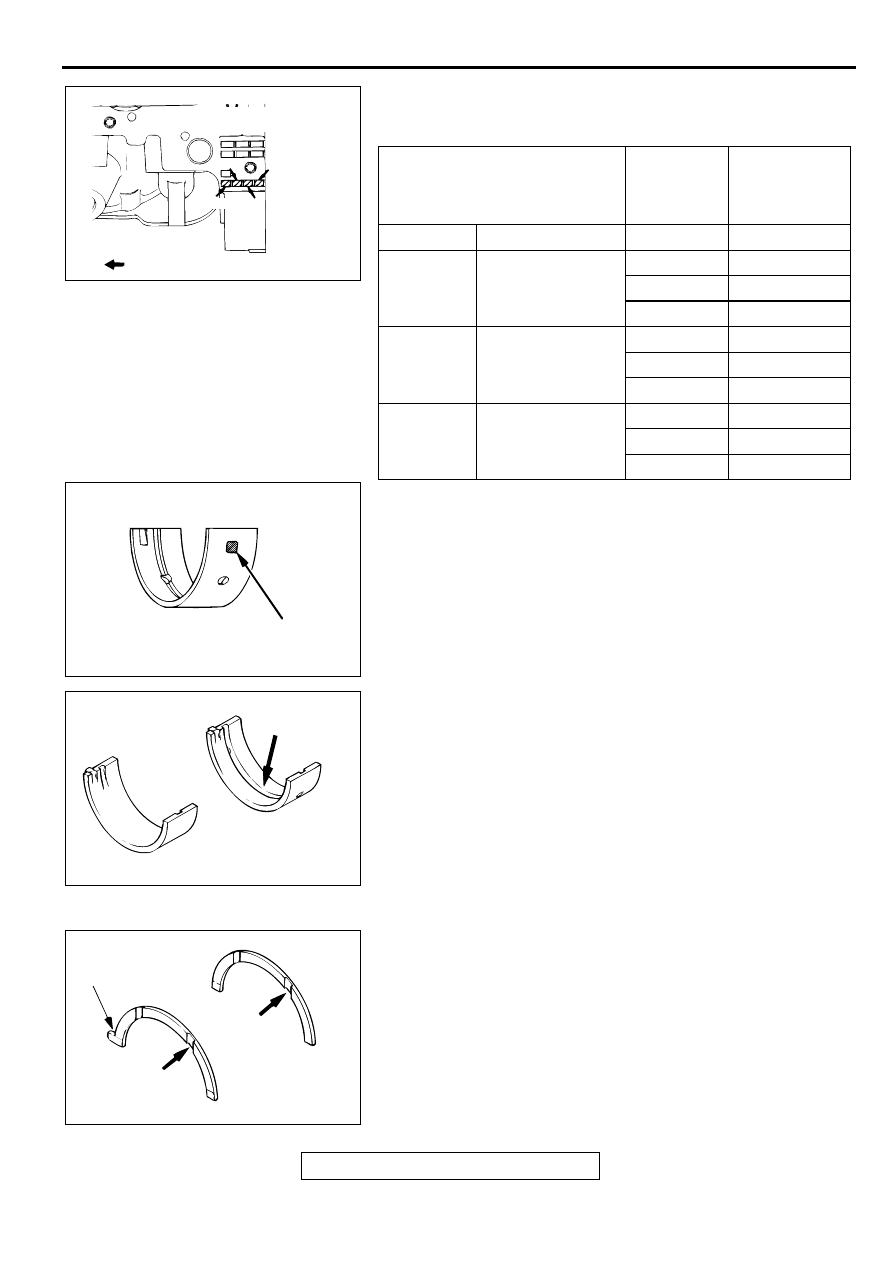
2. The cylinder block bearing bore diameter identification 

marks are stamped at the position shown in the illustration 
from left to right, bearing at No.1.

3. For example, if the crankshaft journal outside diameter ID 

color is "Yellow " and the cylinder block bearing bore ID 
mark is "III," select a bearing whose ID color is "Green."
If there is no ID color paint on the crankshaft, measure the 
journal outside diameter and select a bearing appropriate for 
the measured value.

4. Install the bearings having a groove to the cylinder block.

5. Install the bearings having no groove to the bearing cap.

>>C<< CRANKSHAFT THRUST BEARING INSTALLATION
1. Install the thrust bearings in the number 3 bearing bore in 

the cylinder block and in the bearing cap. For easier 
installation, apply engine oil to the bearings; this will help 
hold them in position.

2. The thrust bearings must be installed with their groove 

toward the crankshaft web. The two thrust bearings are 
different from each other. One has a tab while the other has 
no tab. Be careful not to confuse them.

CRANKSHAFT JOURNAL 
OUTSIDE DIAMETER

CYLINDER 
BLOCK 
BEARING 
BORE

CRANKSHAFT 
BEARING

ID COLOR

SIZE mm (inch)

ID MARK

ID COLOR

Yellow

59.990 

 59.996 

(2.3618 

 2.3620)

I

Pink

II

Red

III

Green

None

59.984 

 59.990 

(2.3616 

 2.3618)

I

Red

II

Green

III

Black

White

59.978 

 59.984 

(2.3613 

 2.3616)

I

Green

II

Black

III

Brown

AKX00648

BEARING BORE 
DIAMETER 
IDENTIFICATION
MARK

CYLINDER INSIDE 
DIAMETER SIZE MARK

TIMING BELT SIDE

AB

No.4

No.2

No.3

No.1

AKX00621

IDENTIFICATION COLOR

AB

AKX00623

GROOVE

FOR UPPER

FOR LOWER

AB

AKX00679

TAB

GROOVE

THRUST BEARING 
"B"

GROOVE

THRUST BEARING "A"

AB

CRANKSHAFT AND CYLINDER BLOCK

TSB Revision

ENGINE OVERHAUL <3.0L ENGINE>

11D-56

>>D<< BEARING CAP/BEARING CAP BOLT INSTALLATION

1. Install the bearing cap on the cylinder block, so that the 

arrow points to the timing belt side.

2. Tighten the bearing cap bolts to 93 

±

 5 N

m (69 

±

 4 ft-lb) in 

the specified tightening sequence.

3. Check that the crankshaft rotates smoothly.
4. Check the end play. If it exceeds the limit value, replace the 

thrust bearing.

Standard value: 0.05 

 0.25 mm (0.002 

 0.009 inch)

Limit: 0.3 mm (0.01 inch)

>>E<< CRANKSHAFT REAR OIL SEAL INSTALLATION
Using special tool MD998718, press-fit a new crankshaft rear 
oil seal into the oil seal case.

AKX00636

BEARING CAP

ARROW

BEARING CAP BOLT NO.
TIGHTENING SEQUENCE

CRANKSHAFT

CYLINDER BLOCK

AB

AKX00722

AKX00693

MD998718

OIL SEAL 
CASE

AB

CRANKSHAFT AND CYLINDER BLOCK

TSB Revision

ENGINE OVERHAUL <3.0L ENGINE>

11D-57

>>F<< OIL SEAL CASE ASSEMBLY INSTALLATION
1. Apply sealant Mitsubishi Genuine Part number MD970389 

or equivalent to the gasket surface of oil seal case.

NOTE: Be sure to install the case quickly while the sealant is 
wet (within 15 minutes).

2. Apply engine oil to the lip of the oil seal, and then install the 

oil seal case onto the cylinder block.

NOTE: After installation, keep the sealed area away from 
the oil for approximately one hour.

INSPECTION

M1113008800043

CRANKSHAFT JOURNAL OIL CLEARANCE (PLASTIC 
GAUGING MATERIAL METHOD)
1. Remove oil from the crankshaft journal and crankshaft 

bearing.

2. Install the crankshaft.

3. Cut plastic gauging material to the same length as the width 

of the bearing and place it on the journal in parallel with its 
axis.

4. Install the crankshaft bearing cap carefully and tighten the 

bolts to the specified torque.

5. Carefully remove the crankshaft bearing cap.

6. Measure the width of the plastic gauging material at its 

widest part by using a scale printed on the plastic gauging 
material package.

Standard value: 0.02 

 0.04 mm (0.0008 

 0.0015 inch)

Limit: 0.1 mm (0.003 inch)

CYLINDER BLOCK 
1. Visually check for scratches, rust, and corrosion. Use also a 

flaw detecting agent for the check. If defects are evident, 
correct, or replace.

2. Using a straightedge and feeler gauge, check the block top 

surface for warpage. Make sure that the surface is free from 
gasket chips and other foreign matter.

Standard value: 0.05 mm (0.002 inch)
Limit: 0.1 mm (0.003 inch)

3. If the distortion is excessive, correct within the allowable 

limit or replace.

Grinding limit: 0.2 mm (0.008 inch) 

*Includes/combined with cylinder head grinding.

AKX00741

AKX00737AB

PLASTIC GAUGING
MATERIAL

AKX00724

AKX00738

CRANKSHAFT AND CYLINDER BLOCK

TSB Revision

ENGINE OVERHAUL <3.0L ENGINE>

11D-58

Cylinder block height (when new): 

210.5 mm (8.29 inches)

4. Check the cylinder walls for scratches and seizure. If defects 

are evident, replace or bore to oversize and replace pistons 
and piston rings.

5. Using a cylinder gauge, measure the cylinder bore and 

cylindricity. If worn badly, correct by boring the cylinders to 
an oversize and replace pistons and piston rings. Measure 
at the points shown in the illustration.

Standard value: 

Cylinder Inside Diameter: 91.1 mm (3.59 inches)
Cylindricity: 0.01 mm (0.0003 inch)

BORING CYLINDER
1. Oversize pistons to be used should be determined on the 

basis of the largest bore cylinder.
Piston size identification

NOTE: Size mark is stamped on the piston top.

2. Measure the outside diameter of the piston to be used. 

Measure it in the thrust direction as shown.

3. Based on the measured piston Outside Diameter (OD), 

calculate the boring finish dimension.

Boring finish dimension = 

Piston OD + (clearance between piston OD and 

cylinder) 

 0.02 mm (0.0008 inch) (honing margin)

CAUTION

To prevent distortion that may result from temperature rise 
during honing, bore cylinders in the order of number 2, 
number 4, number 6, number 1, number 3 and number 5.
4. Bore all cylinders to the calculated boring finish dimension.

5. Hone to the final finish dimension (piston OD + clearance 

between piston OD and cylinder).

6. Check the clearance between the piston and cylinder.

Clearance between piston and cylinder: 

0.02 

 0.04 mm (0.0008 -.0015 inch)

NOTE: When boring cylinders, finish all of six cylinders to 
the same oversize. Do not bore only one cylinder to an 
oversize.

AKX00739

12 mm (0.47 in)

CENTER

AB

BOTTOM

SIZE

IDENTIFICATION 
MARK

0.50 mm (0.02 in) Oversize diameter

0.50

1.00 mm (0.04 in) Oversize diameter

1.00

AKX00740

PISTON OD

THRUST 
DIRECTION

AB


Content   ..  69  70  71  72   ..