Mitsubishi Eclipse / Eclipse Spyder (2000-2002). Service and repair manual - part 28


  Index      Mitsubishi     Mitsubishi Eclipse / Eclipse Spyder (2000-2002). Service and repair manual


Search            


Content   ..  26  27  28  29   ..


Mitsubishi Eclipse / Eclipse Spyder (2000-2002). Service and repair manual - part 28


CYLINDER HEAD GASKET

TSB Revision

ENGINE MECHANICAL <2.4L ENGINE>

11A-29

REMOVAL SERVICE POINTS

<<A>> POWER STEERING OIL PUMP AND BRACKET 
ASSEMBLY REMOVAL
Remove the power steering oil pump and bracket assembly 
from the engine with the hose attached.

NOTE: Place the removed power steering oil pump in a place 
where it will not be a hindrance when removing and installing 
the cylinder head assembly, and secure it with a cord or wire.

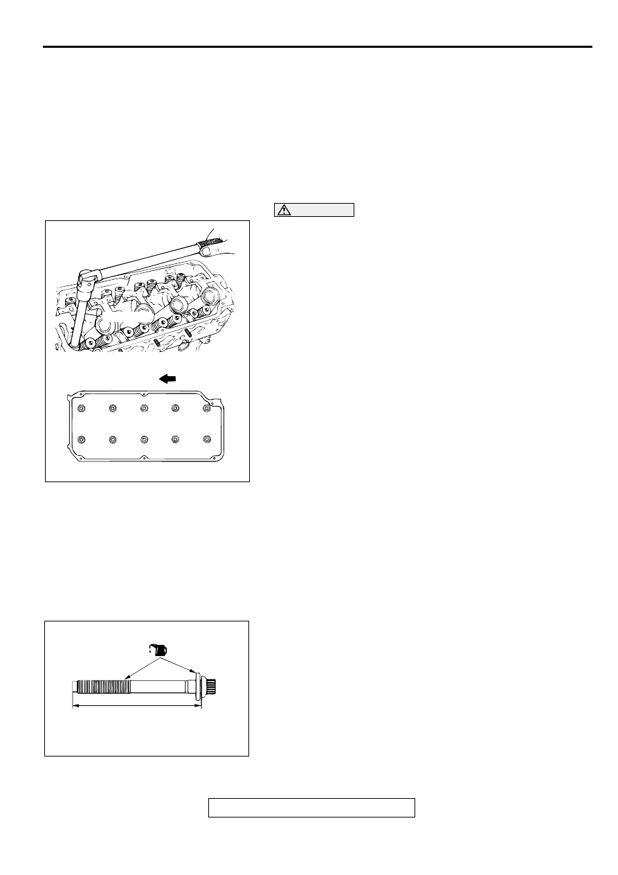
<<B>> CYLINDER HEAD ASSEMBLY REMOVAL

CAUTION

Be careful not to damage or deform the plug guides when 
removing the cylinder head bolts. Plug guides cannot be 
replaced separately.
Using special tool MB991654, loosen the bolts in two or three 
steps in the order of the numbers shown in the illustration, then 
remove the cylinder head assembly.

INSTALLATION SERVICE POINTS

>>A<< CYLINDER HEAD GASKET INSTALLATION
1. Wipe off all oil and grease from the gasket mounting 

surface.

2. Match the shapes of the cylinder head holes with their 

respective cylinder head gasket holes.

>>B<< CYLINDER HEAD ASSEMBLY INSTALLATION
1. When installing the cylinder head bolts, the length below the 

head of the bolts should be within the limit.
If it is outside the limit, replace the bolts.

Limit (A): 99.4 mm (3.91 inches)

2. Apply a small amount of engine oil to the thread section and 

the washer of the cylinder head bolt.

AC000142

INTAKE SIDE

EXHAUST SIDE

FRONT OF
ENGINE

AB

MB991654

1

2

3

5

10

8

7

9

6

4

AC000143

(ENGINE OIL)

AB

A

CYLINDER HEAD GASKET

TSB Revision

ENGINE MECHANICAL <2.4L ENGINE>

11A-30

CAUTION

Always tighten cylinder head bolts at a 90 degree angle. 
If it is less than 90 degree angle, the bolt will loosen.

If it is more than 90 degree angle, remove the head bolt 
and repeat the procedure from step 1.

3. Using special tool MB991654, tighten the bolts by the 

following procedure.

>>C<< HIGH-PRESSURE FUEL HOSE INSTALLATION

CAUTION

Do not allow engine oil to enter the fuel rail.

1. Apply a small amount of new engine oil to the O-ring.

2. While turning the high-pressure fuel hose to the right and 

left, install the fuel rail, while being careful not to damage the 
O-ring. After installing, check that the hose turns smoothly.

3. If the hose does not turn smoothly, the O-ring is probably 

being clamped. Disconnect the high-pressure fuel hose and 
check the O-ring for damage.

4. Re-insert the fuel rail and confirm the hose turns smoothly.

STEP

OPERATION

REMARKS

(1)

Tighten to 79 

±

 4 

N

m (58 

±

 3 ft-lb)

Tighten in the order shown in the 
illustration.

(2)

Fully loosen.

Tighten in the reverse order of 
that shown in the illustration.

(3)

Tighten to 20 

±

 2 

N

m (15 

±

 1 ft-lb)

Tighten in the order shown in the 
illustration.

(4)

Tighten 90

°

 of a 

turn.

Tighten in the order shown in the 
illustration. Mark the head of the 
cylinder head bolt and cylinder 
head with a paint mark.

(5)

Tighten 90

°

 of a 

turn.

Tighten in the order shown in the 
illustration. Check that the 
painted mark of the head bolt is 
aligned with that of the cylinder 
head.

AC000142

INTAKE SIDE

EXHAUST SIDE

FRONT OF
ENGINE

AC

MB991654

10

9

8

6

1

3

4

2

5

7

AC000144

STEP (4)

STEP (5)

90˚

90˚

PAINTED MARKS

PAINTED MARKS

AB

AC000129 AB

FUEL RAIL

HIGH-PRESSURE
FUEL HOSE

O-RING

TIMING BELT

TSB Revision

ENGINE MECHANICAL <2.4L ENGINE>

11A-31

TIM IN G  B ELT

REMOVAL AND INSTALLATION

M1112004300140

Required Special Tools:

MD998738: Adjusting Screw

MD998767: Tensioner Wrench

Pre-removal Operation

Engine Mount Bracket Removal (Refer to GROUP 32, 
Engine Mounting 

P.32-5

.)

Post-installation Operation

Engine Mount Bracket Installation (Refer to GROUP 32, 
Engine Mounting 

P.32-5

.)

Drive Belt Tension Adjustment [Refer to GROUP 00, 
Maintenance Service 

 Drive Belts (Check Condition) 

P.00-40

.]

AC000145

23 ± 3 N·m
17 ± 3 ft-lb

48 ± 6 N·m
36 ± 4 ft-lb

25 ± 4 N·m
18 ± 4 ft-lb

11 ± 1 N·m
96 ± 8 in-lb

14 ± 1 N·m
117 ± 13 in-lb

8.8 ± 1.0 N·m
78 ± 9 in-lb

8.8 ± 1.0 N·m
78 ± 9 in-lb

11 ± 1 N·m
96 ± 8 in-lb

9

7

5

8

4

3

2

1

AB

6

REMOVAL STEPS

1.

DRIVE BELT (POWER STEERING 
OIL PUMP AND A/C COMPRES-
SOR)

2.

DRIVE BELT (GENERATOR)

3.

WATER PUMP PULLEY

4.

CRANKSHAFT PULLEY

5.

TIMING BELT UPPER COVER AS-
SEMBLY

6.

TIMING BELT LOWER COVER 
ASSEMBLY

>>C<<

TIMING BELT TENSION ADJUST-
MENT

<<A>>

>>B<<

7.

TIMING BELT

8.

TENSIONER PULLEY

>>A<<

9.

AUTO-TENSIONER

REMOVAL STEPS (Continued)

TIMING BELT

TSB Revision

ENGINE MECHANICAL <2.4L ENGINE>

11A-32

REMOVAL SERVICE POINT

<<A>> TIMING BELT REMOVAL

CAUTION

The crankshaft should always be turned in the forward 
direction only.
1. Turn the crankshaft in the forward direction (to the right) to 

align the camshaft sprocket timing marks.

2. Loosen the tension pulley fixing bolt.

CAUTION

If the timing belt is to be re-used, use chalk to mark (on its 
flat side) an arrow indicating the clockwise direction.
3. Move the tension pulley to the water pump side, and then 

remove the timing belt.

INSTALLATION SERVICE POINTS

>>A<< AUTO-TENSIONER INSTALLATION
1. Apply 98 

 196 N (22 

 44 pound) force to the pushrod of the 

auto-tensioner by pressing it against a metal object (such as 
the engine block) and measure the movement of the 
pushrod.

Standard value: Within 1 mm (0.04 inch)
A: Length when it is free (not pressed)
B: Length when it is pressed

 B: Movement

2. If it is outside the standard value, replace the auto-tensioner.

CAUTION

Never compress the pushrod too fast, or it may be 
damaged.
3. Use a press or vise to gently compress the auto-tensioner 

pushrod until pin hole A of the pushrod and pin hole B of the 
tensioner cylinder are aligned.

AC000146AB

TIMING MARKS

CAMSHAFT
SPROKET

AC000147

FIXING BOLT

AB

ACX00306AC

A

B

AUTO-TENSIONER

AMOUNT 
PUSHED IN

PUSHROD

98 – 196 N
(22 – 44 lb)

AC000148AB

A

B


Content   ..  26  27  28  29   ..