Mitsubishi Eclipse / Eclipse Spyder (2000-2002). Service and repair manual - part 2


  Index      Mitsubishi     Mitsubishi Eclipse / Eclipse Spyder (2000-2002). Service and repair manual


Search            


Content   ..   1  2  3   ..


Mitsubishi Eclipse / Eclipse Spyder (2000-2002). Service and repair manual - part 2


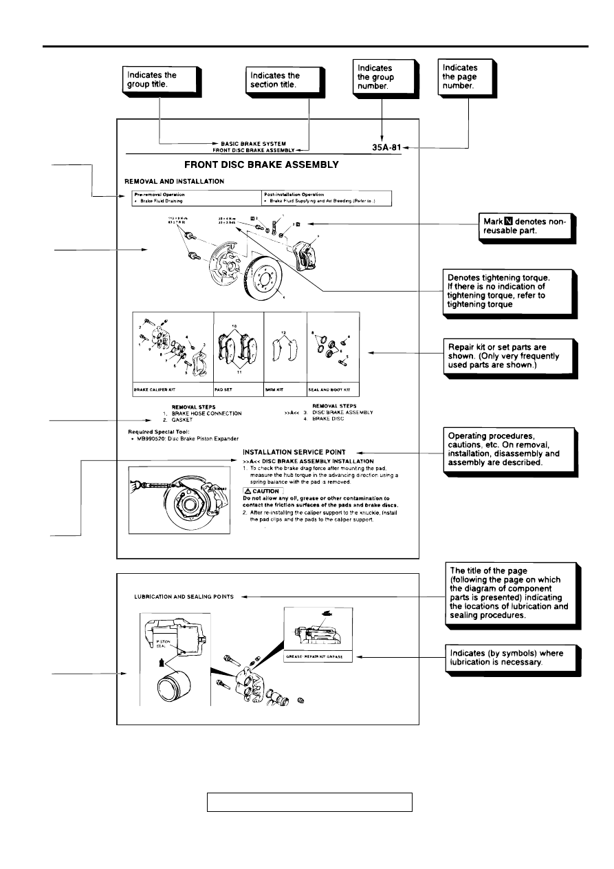
HOW TO USE THIS MANUAL

TSB Revision

GENERAL <BODY AND CHASSIS>

00-5

ACX00860

AC

(continued)

.

TROUBLESHOOTING GUIDELINES

TSB Revision

GENERAL <BODY AND CHASSIS>

00-6

TR O U B LESH O O TIN G  G U ID ELIN ES

M1001008800102

VERIFY THE COMPLAINT

Make sure the customer's complaint and the 
service writer's work order description are 
understood before starting work.

Make sure the correct operation of the system is 
understood. Read the service manual description 
to verify any aspect of normal system operation.

Operate the system to see the symptoms. Look 
for other symptoms that were not reported by the 
customer, or on the work order, that may be 
related to the problem.

DETERMINE POSSIBLE CAUSES

Compare the confirmed symptoms to the diagnostic 
symptom indexes to get to the right diagnosis 
procedure. 
If the confirmed symptoms can not be found on any 
symptom index, determine other possible causes.

Analyze the system diagrams and list all possible 
causes for the problem symptoms.

Rank all these possible causes in order of 
probability, based on how much of the system 
they cover, how likely they are to be the cause, 
and how easy they will be to check. Be sure to 
take experience into account. Consider the 
causes of similar problems seen in the past. The 
list of causes should be ranked in order from 
general to specific, from most-likely to least-likely, 
and from easy-to-check to hard-to-check.

FIND THE PROBLEM

After the symptoms have been confirmed, and 
probable causes have been identified, the next step 
is to make step-by-step checks of the suspected 
system components, junctions, and links in logical 
order.
Use the diagnostic procedures in the service manual 
whenever possible. Follow these procedures 
carefully to avoid missing an important step in the 
diagnosis sequence. It might be the skipped step that 
leads to the solution of the problem.
If the service manual doesn't have step-by-step 
procedures to help diagnose the problem, come up 
with a series of checks based on the ranked list of 
probable causes. Troubleshooting checks should be 
made in the order that the list of causes was ranked:

general to specific

most-likely to least-likely

easy-to-check to hard-to-check

REPAIR THE PROBLEM

When the step-by-step troubleshooting checks find a 
fault, perform the proper repairs. Make sure to fix the 
root cause of the problem, not just the symptom. Just 
fixing the symptom, without fixing the root cause, will 
cause the symptom to eventually return.

VERIFY THE REPAIR

After repairs are made, recheck the operation of the 
system to confirm that the problem is eliminated. 
Make sure to check the system thoroughly. 
Sometimes new problems are revealed after repairs 
have been made.

H O W  TO  U SE TR O U B LESH O O TIN G /IN SPEC TIO N  SERVIC E 

PO IN TS

M1001000200098

Troubleshooting of electronic control systems for 
which the scan tool can be used follows the basic 
outline described below. Even in systems for which 
the scan tool cannot be used, part of these systems 
still follow this outline.

TROUBLESHOOTING CONTENTS

1. STANDARD FLOW OF DIAGNOSTIC 
TROUBLESHOOTING
Troubleshooting strategy are shown.

2. SYSTEM OPERATION AND SYMPTOM 
VERIFICATION TESTS
If verification of the symptoms is difficult, procedures 
for checking operation and verifying symptoms are 
shown.

3. DIAGNOSTIC FUNCTION
The following trouble code diagnosis are shown.

How to read diagnostic trouble codes

How to erase diagnostic trouble codes

Input inspection service points

HOW TO USE TROUBLESHOOTING/INSPECTION SERVICE POINTS

TSB Revision

GENERAL <BODY AND CHASSIS>

00-7

4. DIAGNOSTIC TROUBLE CODE CHART

5. SYMPTOM CHART
If there are symptoms, even though the results of 
inspection using the scan tool show that all 
diagnostic trouble codes are normal, inspection 
procedures for each symptom will be found by using 
this chart.

6. DIAGNOSTIC TROUBLE CODE PROCEDURES
Indicates the inspection procedures corresponding to 
each diagnostic trouble code. (Refer to 

P.00-7

.)

7. SYMPTOM PROCEDURES
Indicates the inspection procedures corresponding to 
each symptoms classified in the Symptom Chart. 
(Refer t

P.00-7

.)

8. SERVICE DATA REFERENCE TABLE
Inspection items and normal judgement values have 
been provided in this chart as reference information.

9. CHECK AT ECU TERMINALS
Terminal numbers for the ECU connectors, 
inspection items and standard values have been 
provided in this chart as reference information.

Terminal Voltage Checks
1. Connect a needle-nosed wire probe to a voltmeter 

probe.

CAUTION

Short-circuiting the positive (+) probe between a 
connector terminal and ground could damage 
the vehicle wiring, the sensor, the ECU, or all 
three. Use care to prevent this!
2. Insert the needle-nosed wire probe into each of 

the ECU connector terminals from the wire side, 
and measure the voltage while referring to the 
check chart.

NOTE: Measure voltage with the ECU connectors 
connected.
You may find it convenient to pull out the ECU to 
make it easier to reach the connector terminals.

Checks don't have to be carried out in the order 
given in the chart.

3. If voltage readings differ from normal condition 

values, check related sensors, actuators, and 
wiring, then replace or repair.

4. After repair or replacement, recheck with the 

voltmeter to confirm that the repair has corrected 
the problem.

Terminal Resistance and Continuity Checks 
1. Turn the ignition switch to "LOCK" (OFF) position.

2. Disconnect the ECU connector.

CAUTION

If resistance and continuity checks are 
performed on the wrong terminals, damage to 
the vehicle wiring, sensors, ECU, and/or 
ohmmeter may occur. Use care to prevent this!
3. Measure the resistance and check for continuity 

between the terminals of the ECU harness-side 
connector while referring to the check chart.

NOTE: Checks don't have to be carried out in the 
order given in the chart.

4. If the ohmmeter shows any deviation from the 

Normal Condition value, check the corresponding 
sensor, actuator and related electrical wiring, then 
repair or replace.

5. After repair or replacement, recheck with the 

ohmmeter to confirm that the repair has corrected 
the problem.

10. INSPECTION PROCEDURES USING AN 
OSCILLOSCOPE
When there are inspection procedures using an 
oscilloscope, these are listed here.

HOW TO USE THE INSPECTION 
PROCEDURES

The causes of many of problems occurring in electric 
circuitry are generally the connectors, components, 
the ECU and the harnesses between connectors, in 
that order. These inspection procedures follow this 
order. They first try to discover a problem with a 
connector or a defective component.

HOW TO USE TROUBLESHOOTING/INSPECTION SERVICE POINTS

TSB Revision

GENERAL <BODY AND CHASSIS>

00-8

ACX00861AC

(1) Relevanta circuit(s) of the component which
      the DTC indicates are described.

(2) Shows the position of the connector(s) which
      are referred to in the above circuit(s).

(3) Explains about the operation principle of the
      component or its relevant parts in that circuit.


Content   ..   1  2  3   ..