Index Mitsubishi Mitsubishi Eclipse. Technical Information Manual (1994)
Search
Content .. 92 93 94 95 ..
Mitsubishi Eclipse. Technical Information Manual (1994) - part 94
EQUIPMENT Heater and Air Conditioning
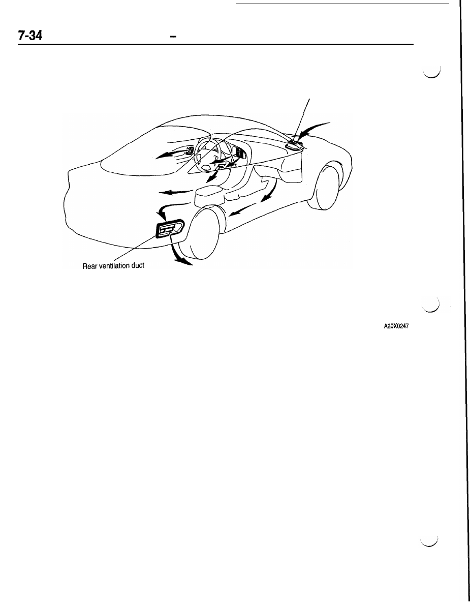
<VENTILATION>
Air guide duct