Mitsubishi Eclipse. Technical Information Manual (1994) - part 67


  Index      Mitsubishi     Mitsubishi Eclipse. Technical Information Manual (1994)


Search            


Content   ..  65  66  67  68   ..


Mitsubishi Eclipse. Technical Information Manual (1994) - part 67


DRIVE-CONTROL COMPONENTS   ABS 

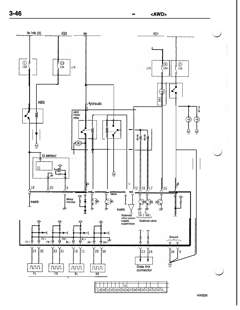
ABS ELECTRICAL CIRCUIT DIAGRAM

Ignition

switch 

Ignition

F u s i b l e   l i n k   ( 2 )

switch ,

Fusib i  

Fusit

link (9)

Dedicated


fuse

Dedicated

fuse

Combination
meter

Stop light

switch

 power

relay

Diode

rnit (HU)

5

7

ABS

valve

relay

2 6

7

Motor

relay

relay

Motor 

7

power

stop
light


I

1

Solenoid
valve

ABS-ECU

r

ECU power

2

4

Resistor

29

Wheel speed sensor

1

2

3

4

5

6

7

9 10 11 12 13 14 15 16 17 18

ABS-ECU Connector Pin Configuration

DRIVE-CONTROL COMPONENTS   ABS 

ABS HYDRAULIC FUNCTION SCHEMATIC

The ABS in the AWD models is of two-channel sys-
tem (two-fluid pressure system).   this system, the
solenoid valves are energized or de-energized so
that the front and rear wheel brakes on the same

side are controlled on the “Select Low” rule.

For example, when either the front or rear wheel

on the right side is about to be locked, all the solenoid
valves on the right side, including those on the front

right wheel, are controlled to hold or slightly reduce

the fluid pressure. In order to prevent one wheel

locking state in the rear wheels, it is necessary

to control the rear wheels by Select Low as in the

FWD vehicles. In the case of the AWD vehicles,

the rear right and left wheels are subject to Select

Low control by the Select Low valves. As a result,

the fluid pressure for a total of three wheels (the
front right wheel and the rear right and left wheels)

are under simultaneous control.
Select-low: this is a method of providing the same
hydraulic control to both wheels when either wheel

is about to lock, matching it to the side about to
lock, or a method to control by matching pressure

to the low side.

Master cylinder

Wheel speed sensor (FR)

 sensor (FL)

 sensor (FL)

Wheel 

Hydraulic Unit (HU)

Hydraulic Unit (HU)

Front left wheel

Front right wheel

Solenoid

valve control

Solenoid

valve control

Select Low

R e s e r v o i r  

Select Low

I

n

Wheel speed
sensor (RR)

Rear right wheel

Rear left wheel 

DRIVE-CONTROL COMPONENTS   ABS 

REAR

Knuckle

Rotor

0

Drive shaft

 Speed

sensor

S E N S O R

WHEEL SPEED SENSOR
The wheel speed sensor of the AWD vehicle is the same as

in the FWD vehicle, except that the rear rotor is mounted on

the drive shaft. (Refer to P. 3-31.)

STOP LIGHT SWITCH
The same as in the FWD vehicle. (Refer to P. 3-31.)

G SENSOR
The G sensor, mounted inside the center console panel, detects
the longitudinal acceleration/deceleration (body G) of the ve-
hicle body.

Construction and operation
The inside of the sensor is shown at left. A semiconductor
strain gauge has been adopted as the sensor.

DRIVE-CONTROL COMPONENTS   ABS 

Piezo diffusion
resistor

Weight

Damping

oil

Bridge circuit

Piezo diffusion
resistor

-0.1

0

1.0


 Rate of 

 Decele-

ration

acceleration

ration

output

characteristics

Output voltage (V)

I

The semiconductor strain gauge type sensor, constructed as
shown at the left, consists of a weight mounted at the free

end of an N-type silicon leaf spring, and four P-type diffusion
layers made on the surface of the leaf spring to constitute
piezo diffusion resistors. The case is filled with a damping
oil to prevent breakdown that may be caused by resonance.

The piezo diffusion resistors, arranged as shown at the left,
complete a bridge circuit which constitutes a semiconductor
strain gauge.
When the sensor is placed under strain by acceleration, the

piezoelectric effect changes its electrical resistance, causing

the bridge circuit to go out of balance.

If a voltage is applied across the bridge circuit, the acceleration

can be measured by detecting the amount the bridge circuit
goes out of balance in terms of a change in the voltage.

The output characteristics vary as shown at the left in the
direction of acceleration with 2.5 V as 0 G.


Content   ..  65  66  67  68   ..