Mitsubishi Eclipse. Technical Information Manual (1994) - part 60
DRIVE-CONTROL COMPONENTS Power Steering
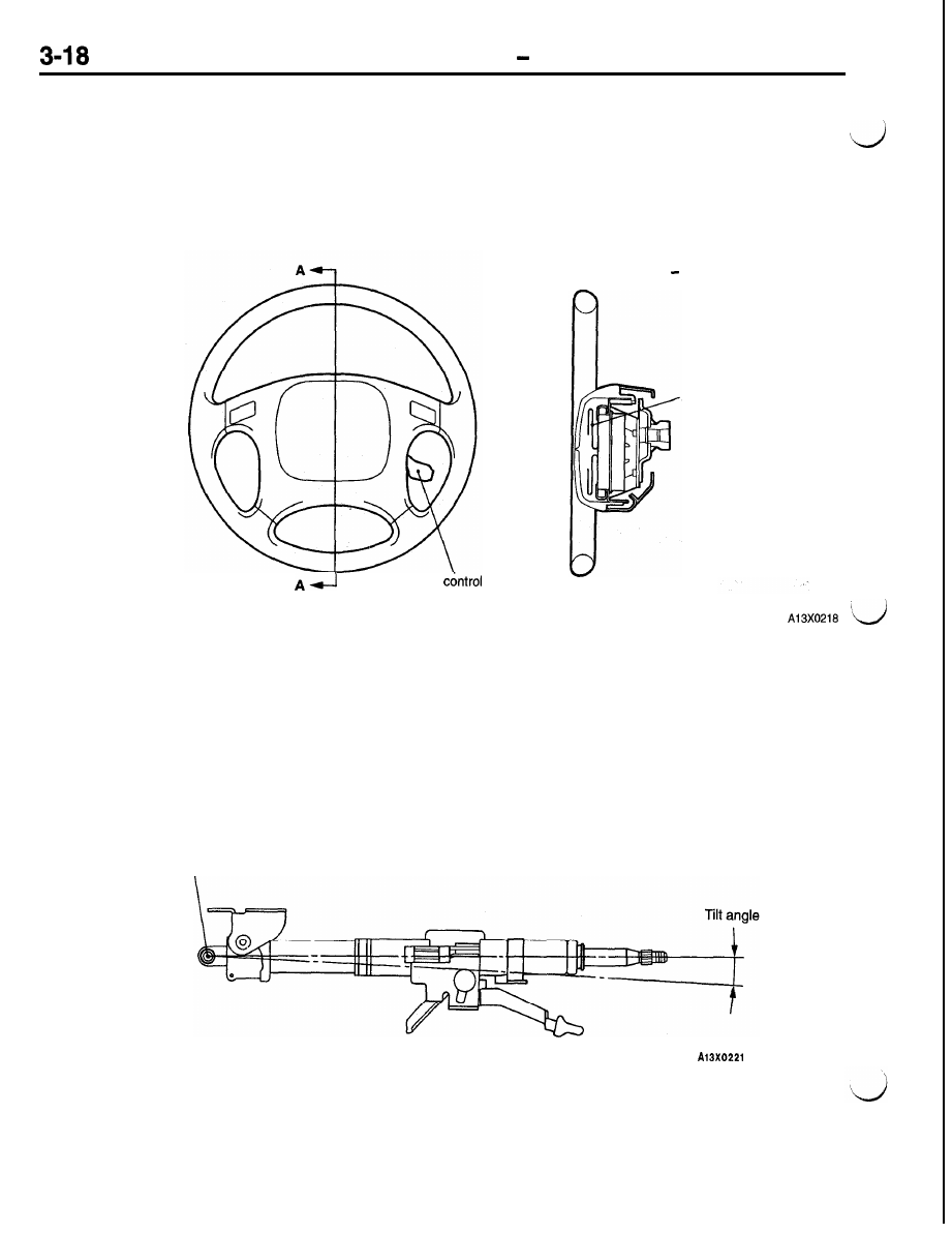
STEERING WHEEL
The steering wheel have the following features to
provide excellent maneuverability and stability.
l
The steering wheel has been specially designed
for improved maneuverability and good view
of meters. Some model versions come with a
steering wheel with auto-cruise control switches
on it.
l
The air bag incorporated in the steering wheel
provides the driver with additional protection
against the shock from a front-end collision.
Auto-cruise
switch
Cross section A A
Air bag
STEERING SHAFT AND COLUMN
All model versions come standard with a tilt steering
mechanism which allows the driver to select an
optimum driving position. Also adopted is an impact
absorption mechanism to absorb impact energy in
a collision, thereby ensuring the safety of the driver.
Tilting fulcrum