Mitsubishi Eclipse. Technical Information Manual (1994) - part 18
ENGINE <NON-TURBO> Control System
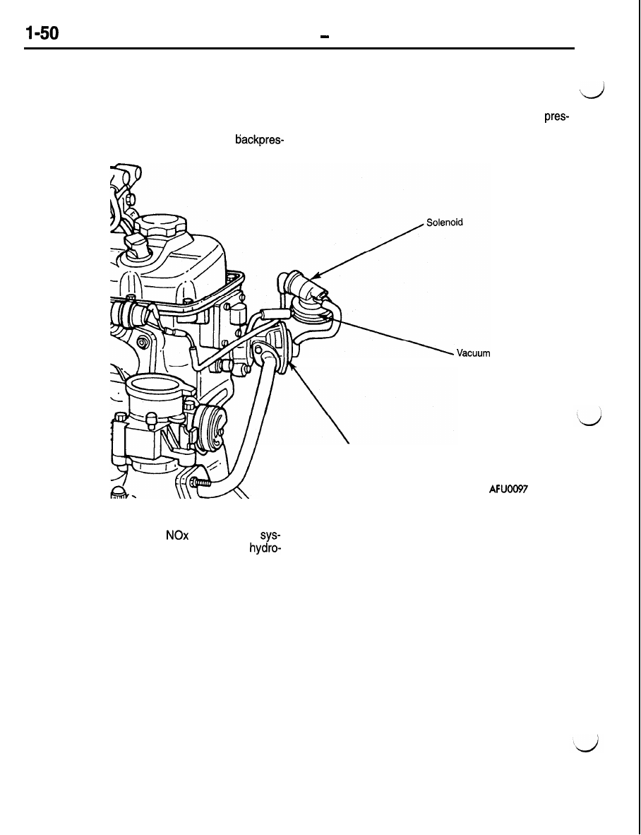
Operation
The EGR system consists of a vacuum solenoid,
back pressure transducer and a vacuum operated
sure causes the transducer diaphragm to modulate.
valve. When activated, the solenoid allows vacuum
This allows intake manifold vacuum to reach the
to flow to the transducer. Negative exhaust back-
EGR valve. The combination of vacuum on one
pressure allows manifold vacuum from the solenoid
side of the valve diaphragm and exhaust back
to vent to atmosphere. Positive exhaust
sure on the other allows exhaust gases to be
introduced into the intake manifold.
transducer
EGR valve
An EGR system stuck in the closed position prevents
the system from decreasing
emissions. A
tern stuck in the open position can increase
carbon emissions, fuel consumption, and produce
rough engine operation.