Mitsubishi Eclipse. Technical Information Manual (1994) - part 12


  Index      Mitsubishi     Mitsubishi Eclipse. Technical Information Manual (1994)


Search            


Content   ..  10  11  12  13   ..


Mitsubishi Eclipse. Technical Information Manual (1994) - part 12


1-26

ENGINE <NON-TURBO>   Control System

ACTUATORS AND CONTROL

FUEL INJECTORS

The 

 engine uses electrically operated top feed

fuel injectors. The MFI relay (automatic shut down

relay) supplies battery voltage to the fuel injectors.

The PCM controls the ground path for each injector

in sequence. By switching the ground paths on and
off, the PCM fine-tunes injector pulse width. Injector
pulse width refers to the amount of time an injector
operates.

The PCM determines injector synchronization from
the camshaft position sensor and crankshaft position

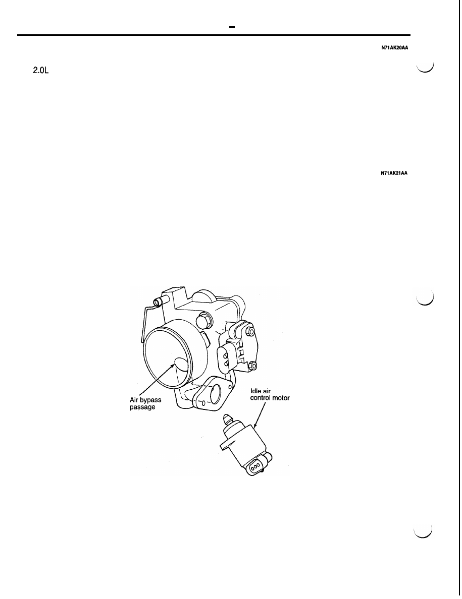
IDLE AIR CONTROL MOTOR

The idle air control (IAC) motor is mounted on the
throttle body. The PCM operates the idle air control

motor. The PCM adjusts engine idle speed through

the idle air control motor to compensate for engine

load or ambient conditions.

The throttle body has an air bypass passage that

provides air for the engine during closed throttle
idle. The idle air control motor pintle protrudes into

the air bypass passage and regulates air flow
through it.

sensor inputs. The PCM grounds the MFI and fuel
pump relays after receiving the camshaft position
sensor and crankshaft position sensor inputs.

The PCM energizes the injectors in a sequential
order during all engine operating conditions except
start-up. For the first injector pulse width during
start-up, all injectors are energized at the same
time. Once the PCM determines crankshaft position,

it beings energizing the injectors in sequence.

The PCM adjusts engine idle speed by moving the

IAC motor pintle in and out of the bypass passage.

The adjustments are based on inputs the PCM re-
ceives. The inputs include the throttle position sen-
sor, crankshaft position sensor, coolant temperature
sensor, vehicle speed sensor and various switch
operations (brake, park/neutral, air conditioning,

power steering).

AFU0079


   Control Svstem

IGNITION COIL

The coil assembly consists of 2 coils molded 
er. The coil assembly is mounted on the cylinder
head cover. High tension leads route to each cylinder
from the coil. The coil fires two spark plugs every
power stroke. One plug is the cylinder under com-
pression, the other cylinder fires on the exhaust
stroke. Coil number one fires cylinders 1 and 4.
Coil number two fires cylinders 2 and 3. The 
train control module (PCM) determines which of
the coils to charge and fire at the correct time.

The MFI relay (automatic shut down relay) provides
battery voltage to the ignition coil. The PCM provides
a ground contact (circuit) for energizing the coil.
When the PCM breaks the contact, the energy in
the coil primary transfers to the secondary causing
the spark. The PCM will de-energize the MFI relay
if it does not receive the crankshaft position sensor
and camshaft position sensor inputs. Refer to MFI

Relay PCM Output in this section for relay operation.

MFI RELAY (Automatic Shut Down)

The MFI relay (automatic shut down relay) supplies

battery voltage to the fuel injectors, electronic igni-

tion coil, generator, and the heating elements in
the oxygen sensors.

The PCM controls the relay by switching the ground
path for the solenoid side of the relay on and off.
The PCM turns the ground path off when the ignition
switch is in the Off position. When the ignition switch

is in the On or Crank position, the PCM monitors

the crankshaft position sensor and camshaft position
sensor signals to determine engine speed and igni-
tion timing (coil dwell). If the PCM does not receive
the crankshaft position sensor and camshaft position
sensor signals when the ignition switch is in the

Run position, it will de-energize the MFI relay.

Along with the fuel pump relay, the MFI relay at-
taches to a bracket on the drivers side of the dash

panel.

 Fuel 

MFI relay 

0

Strut
tower

ENGINE <NON-TURBO> 

 Control System

FUEL PUMP RELAY

The fuel pump relay supplies battery voltage to the
fuel pump. The PCM controls the fuel pump relay

by switching the ground path for the solenoid side
of the relay on and off. The PCM turns the ground
path off when the ignition switch is in the Off position.

When the ignition switch is in the On position, the

PCM energizes the fuel pump. If the crankshaft

position sensor does not detect engine rotation,
the PCM de-energizes the relay after’approximately
one second.

Along with the MFI relay, the fuel pump relay 
taches  to a bracket on the drivers side of the dash
panel.

AIR CONDITIONING CLUTCH RELAY

The PCM provides the ground path for the relay
coil. Relay operation is based on inputs the PCM

receives from the air conditioning switch. The PCM
deactivates the relay at vehicle start-up and also

N7lAK24AA

if it senses a part throttle/wide open throttle launch
condition. This temporarily reduces the accessory
load on the engine.

RADIATOR  FAN RELAY AND  AIR CONDlTIONING CONDENSER FAN RELAY (High, 

LOW) 

The PCM operates the relay based on inputs from

The PCM supplies the ground circuit for the High/

the engine coolant temperature sensor, vehicle

Low relay coil to operate the fan motor in high/low

speed sensor and A/C system.

speeds.

CHARGING SYSTEM INDICATOR LAMP

The PCM controls operation of the charging system

indicator lamp located in the vehicle’s instrument

cluster. The PCM provides a ground to complete
the lamp circuit if the charging output falls below
a specified threshold.

The PCM also supplies the ground circuit for the

lamp circuit for 3 seconds after the ignition switch
is turned to the ON position and illuminates the
indicator lamp.

TACHOMETER

The PCM operates the tachometer on the instrument
panel. The PCM calculates engine RPM from the

crankshaft position sensor input.

GENERATOR

The PCM controls the generator field current to

regulate the generator output voltage to the target

voltages in accordance with the battery tempera-
tures.

ENGINE <NON-TURBO> 

 Control System

1-29

DUTY CYCLE EVAP PURGE SOLENOID

The duty cycle EVAP purge solenoid regulates the

rate of vapor flow from the EVAP canister to the

throttle body. The power-train control module oper-
ates the solenoid.

During the cold start warm-up period and the hot

start time delay, the PCM does not energize the
solenoid. When de-energized, no vapors are purged.
The PCM de-energizes the solenoid during Open

Loop operation.

The engine enters Closed Loop operation after it

reaches a specified temperature and the 


grammed time delay ends. During Closed Loop op-
eration, the PCM energizes and de-energizes the
solenoid 5 to 10 times per second, depending upon
operating conditions. The PCM varies the vapor
flow rate by changing solenoid pulse width. Pulse
width is the amount of time the solenoid is de-ener-
gized.

The solenoid attaches to a bracket next to the EVAP
canister. The canister is located ahead of the pas-

senger’s front wheel well.


Content   ..  10  11  12  13   ..