Mitsubishi Eclipse. Technical Information Manual (1994) - part 6
ENGINE <NON-TURBO>
- General Information
ENGINE <NON-TURBO>
GENERAL INFORMATION
This 420A
engine is a product of Chrysler Corporation. It is not equipped with a turbocharger.
MAJOR SPECIFICATIONS
Items
Specifications
Total displacement
1,996 (121.8)
Bore x Stroke
mm (in.)
87.5 (3.45) x 83.0 (3.27)
Compression ratio
9.6
Camshaft arrangement
DOHC
Valve timing
At 0.5 mm
in.) lift
Intake
Open
1.3” BTDC
Close
39.7” ABDC
Exhaust
Open
36” BBDC
Close
1.1” ATDC
Rocker arm
Roller type
Lash adjuster
Equipped
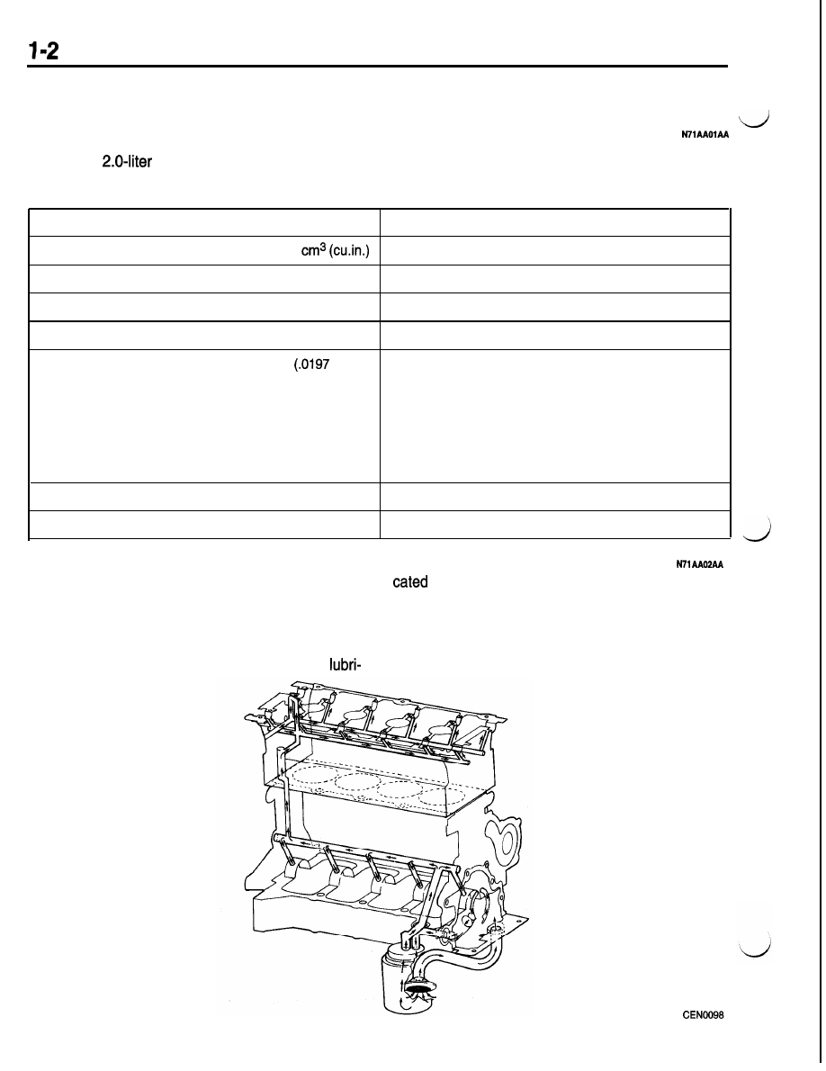
LUBRICATION SYSTEM
System is full flow filtration, pressure feed type.
The oil pump is mounted in the front engine cover
from rod bearing throw-off and slinger slots
and driven by the crankshaft. Pressurized oil is then
on the connecting rod assemblies. Camshaft and
routed through the main oil gallery, running the
valve mechanisms are lubricated from a full-length
length of the cylinder block, supplying main and
cylinder head oil gallery supplied from the crankcase
main oil gallery.
rod bearings with further routing. Pistons are