Mitsubishi Eclipse. Manual - part 827


  Index      Mitsubishi     Mitsubishi Eclipse - service repair manual 2004 year


Search            


Content   ..  825  826  827  828   ..


Mitsubishi Eclipse. Manual - part 827


AUTOMATIC TRANSAXLE DIAGNOSIS

TSB Revision

AUTOMATIC TRANSAXLE

23A-317

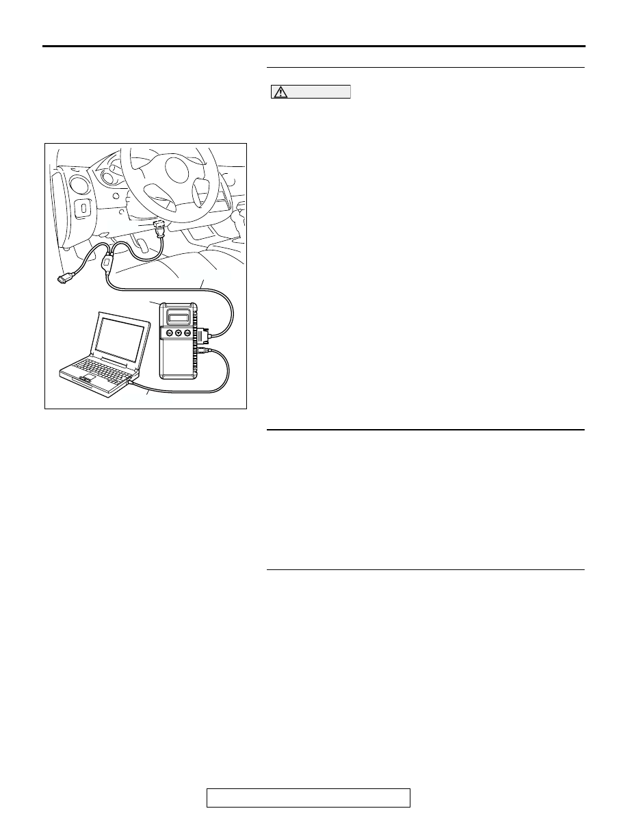
STEP 1. Using scan tool MB991958, check actuator test.

CAUTION

To prevent damage to scan tool MB991958, always turn the 
ignition switch to the "LOCK" (OFF) position before con-
necting or disconnecting scan tool MB991958. 
(1) Connect scan tool MB991958 to the data link connector.
(2) Turn the ignition switch to the "ON" position.
(3) Set scan tool MB991958 to actuator test mode for following 

items.

a. Item 01: Low-reverse solenoid valve
b. Item 02: Underdrive solenoid valve

c. Item 03: Second solenoid valve

d. Item 04: Overdrive solenoid valve

• An audible clicking or buzzing should be heard when 

the solenoid valves are energized.

(4) Turn the ignition switch to the "LOCK" (OFF) position.
Q: Are the solenoid valves operating properly?

YES : Go to Step 2.
NO :  Repair or replace the solenoid valves. Refer to 

GROUP 23B, Valve Body 

P.23B-74

. Then confirm 

that the symptom is eliminated.

STEP 2. Check the hydraulic pressure.
(1) Measure the hydraulic pressure of each element. Check if 

each hydraulic pressure is within the standard value. Refer 
to 

P.23A-28

, Hydraulic Pressure Test.

(2) If some elements pressure are within the standard value 

and some are not, recheck the symptom.

Q: Are all hydraulic pressures within the standard value?

YES : Go to Step 6.
NO :  Go to Step 3.

STEP 3. Adjust the line pressure.
Adjust the line pressure. Refer to 

P.23A-41

, Line Pressure 

Adjustment. Then check the symptom.
Q: Is the symptom eliminated?

YES : The procedure is complete.
NO :  Go to Step 4.

AC303127

AB

MB991911

16-PIN

MB991827

MB991824 

AUTOMATIC TRANSAXLE DIAGNOSIS

TSB Revision

AUTOMATIC TRANSAXLE

23A-318

STEP 4. Replace the oil pump.
(1) Remove the transaxle.
(2) Replace the oil pump. (Oil pump can not be repaired). Refer 

to GROUP 23B, Transaxle 

P.23B-10

. Then check the 

symptom.

Q: Is the symptom eliminated?

YES : The procedure is complete.
NO :  Go to Step 5.

STEP 5. Disassemble and clean the valve body.
Check the O-ring installation bolts for looseness and the valve 
body for damage. Repair or replace the faulty parts. Refer to 
GROUP 23B, Valve Body 

P.23B-74

.

Replace the valve body assembly if the damages are thought 
to be irreparable. Then check the symptom.
Q: Is the symptom eliminated?

YES : The procedure is complete.
NO :  Go to Step 7.

STEP 6. Check each brake and clutch.
(1) Remove the transaxle.
(2) Check the facing for seizure and piston seal ring for 

damage and interference with retainer. Repair or replace 
the faulty parts. Refer to GROUP 23B, Transaxle 

P.23B-10

Underdrive Clutch and Input Shaft 

P.23B-57

, Reverse and 

Overdrive Clutch 

P.23B-59

. Then check for the symptom.

Q: Is the symptom eliminated?

YES : The procedure is complete.
NO :  Go to Step 7.

STEP 7. Replace the PCM.
Q: Is the symptom eliminated?

YES : The procedure is complete.
NO :  Start over at Step 1.

AC001865

AC001860 AB

VALVE
BODY
ASSEMBLY

AC001868

REVERSE
CLUTCH

SECOND
BRAKE

LOW-
REVERSE
BRAKE

UNDERDRIVE
CLUTCH

OVERDRIVE CLUTCH

AB

AUTOMATIC TRANSAXLE DIAGNOSIS

TSB Revision

AUTOMATIC TRANSAXLE

23A-319

INSPECTION PROCEDURE 10: Early or Late Shifting All Gears

.

COMMENT
If all shift points are early or late while driving, the 
cause is probably a malfunction of the output shaft 
speed sensor, TP sensor or a solenoid valve.

.

TROUBLESHOOTING HINTS (The most likely 
causes for this case:)

• Malfunction of the output shaft speed sensor

• Malfunction of the TP sensor

• Malfunction of each solenoid valve

• Abnormal line pressure

• Malfunction of the valve body

• Malfunction of the PCM

DIAGNOSIS

Required Special Tool:

•  MB991958: Scan Tool (MUT-III Sub Assembly)

• MB991824: V.C.I.

• MB991827: MUT-III USB Cable

• MB991911: MUT-III Main Harness B

STEP 1. Using scan tool MB991958, check data list item 23: 
Output Shaft Speed Sensor.

CAUTION

To prevent damage to scan tool MB991958, always turn the 
ignition switch to the "LOCK" (OFF) position before con-
necting or disconnecting scan tool MB991958. 
(1) Connect scan tool MB991958 to the data link connector.
(2) Start the engine.
(3) Set scan tool MB991958 to data reading mode for item 23: 

Output Shaft Speed Sensor.

• When driving at constant speed of 50km/h (31mph), the 

display should be 1,600 

− 1,900 r/min <2.4L Engine>, 

1,300 

− 1,600 r/min <3.0L Engine>. (Gear range: 3rd 

gear)

(4) Turn the ignition switch to the "LOCK" (OFF) position.
Q: Is the sensor operating properly?

YES : Go to Step 2.
NO :  Refer to 

P.23A-131

DTC 23: Output shaft speed 

sensor system.

AC303127

AB

MB991911

16-PIN

MB991827

MB991824 

AUTOMATIC TRANSAXLE DIAGNOSIS

TSB Revision

AUTOMATIC TRANSAXLE

23A-320

STEP 2. Using scan tool MB991958, check data list item 11: 
TP Sensor.
(1) Connect scan tool MB991958 to the data link connector.
(2) Turn the ignition switch to the "ON" position.
(3) Set scan tool MB991958 to data reading mode for item 11: 

TP Sensor.

• With the throttle valve in idle position, voltage should 

measure between 535 and 735 mV.

• With the throttle valve in full-open position, voltage 

should measure between 4,500 and 5,500 mV.

(4) Turn the ignition switch to the "LOCK" (OFF) position.
Q: Is the measured voltage between 535 and 735 mV at 

idle, and between 4,500 and 5,500 mV in the full-open 
position?
YES : 
Go to Step 3.
NO :  Check the TP sensor. Refer to 

P.23A-43

P.23A-54

P.23A-64

DTCs 11, 12, 14: TP Sensor System. Then 

check the malfunction.

STEP 3. Using scan tool MB991958, check data list.
(1) Connect scan tool MB991958 to the data link connector.
(2) Start the engine.
(3) Set scan tool MB991958 to data reading mode for following 

items.

a. Item 31: Low-Reverse Solenoid Valve Duty Percent
b. Item 32: Underdrive Solenoid Valve Duty Percent

c. Item 33: Second Solenoid Valve Duty Percent

d. Item 34: Overdrive Solenoid Valve Duty Percent

• Check that the values shown below are displayed 

when each data list item is entered.

AC303127

AB

MB991911

16-PIN

MB991827

MB991824 

AC303127

AB

MB991911

16-PIN

MB991827

MB991824 

DRIVING CONDITION

DATA LIST ITEM
31

32

33

34

Driving at constant speed of 10 km/h (6.2 mph) in 1st gear

0%

0%

100%

100%

Driving at constant speed of 30 km/h (19 mph) in 2nd gear

100%

0%

0%

100%

Driving at constant speed of 50 km/h (31 mph) in 3rd gear

100%

0%

100%

0%

Driving at constant speed of 50 km/h (31 mph) in 4th gear

100%

100%

0%

0%


Content   ..  825  826  827  828   ..