Mitsubishi Eclipse. Manual - part 787
AUTOMATIC TRANSAXLE DIAGNOSIS
TSB Revision
AUTOMATIC TRANSAXLE
23A-157
AC001844
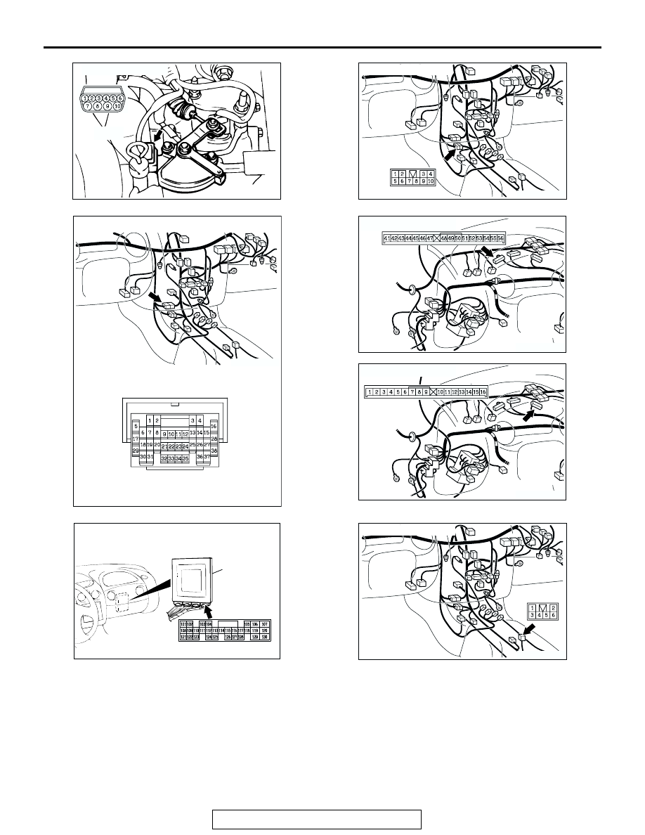
CONNECTOR: B-41
DIPSTICK
AK
B-41
AC001741
CONNECTOR: C-27
AR
C-27
AC106611AB
CONNECTOR: C-28
C-28
AC001729AX
CONNECTOR: C-41
C-41
AC001729AW
CONNECTOR: C-43
C-43
AC001657
CONNECTOR: C-61 <2.4L ENGINE> OR
C-63 <3.0L ENGINE>
PCM
BC
C-61 <2.4L ENGINE> OR C-63 <3.0L ENGINE>
AC001741
CONNECTOR: C-65
AS
C-65