Mitsubishi Eclipse. Manual - part 783


  Index      Mitsubishi     Mitsubishi Eclipse - service repair manual 2004 year


Search            


Content   ..  781  782  783  784   ..


Mitsubishi Eclipse. Manual - part 783


AUTOMATIC TRANSAXLE DIAGNOSIS

TSB Revision

AUTOMATIC TRANSAXLE

23A-141

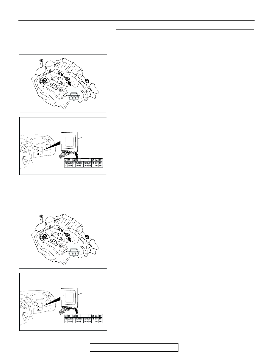
STEP 9. Check output shaft speed sensor connector B-38 
and PCM connector C-61 <2.4L Engine> or C-63 <3.0L 
Engine> for loose, corroded or damaged terminals, or 
terminals pushed back in the connector.
Q: Are the connectors and terminals in good condition?

YES : Go to Step 10.
NO :  Repair or replace the damages components. Refer to 

GROUP 00E, Harness Connector Inspection 

P.00E-2

.

STEP 10. Check the harness for short circuit to ground 
between output shaft speed sensor connector B-38 
terminal 2 and PCM connector C-61 <2.4L Engine> or C-63 
<3.0L Engine> terminal 104.
Q: Is the harness wire in good condition?

YES : Go to Step 11.
NO :  Repair or replace the harness wire.

AC001837AI

CONNECTOR: B-38

B-38

AC001657

CONNECTOR: C-61 <2.4L ENGINE> OR
C-63 <3.0L ENGINE>

PCM

BC

C-61 <2.4L ENGINE> OR C-63 <3.0L ENGINE>

AC001837AI

CONNECTOR: B-38

B-38

AC001657

CONNECTOR: C-61 <2.4L ENGINE> OR
C-63 <3.0L ENGINE>

PCM

BC

C-61 <2.4L ENGINE> OR C-63 <3.0L ENGINE>

AUTOMATIC TRANSAXLE DIAGNOSIS

TSB Revision

AUTOMATIC TRANSAXLE

23A-142

STEP 11. Measure the ground circuit for resistance at the 
output shaft speed sensor connector B-38.
(1) Disconnect connector B-38 from the speed sensor and 

measure at the harness side.

(2) Measure the resistance between terminal 1 and ground.

• The resistance should measure less than 2 ohms.

Q: Is the measured resistance less than 2 ohms?

YES : Go to Step 16.
NO :  Go to Step 12.

STEP 12. Measure the resistance at the PCM connector 
C-50 <2.4L Engine> or C-52 <3.0L Engine> by backprobing.
(1) Do not disconnect connector C-50 <2.4L Engine> or C-52 

<3.0L Engine>.

(2) Turn the ignition switch to the "ON" position.

(3) Measure the resistance between terminal 16 and ground by 

backprobing.

• The resistance should measure less than 2 ohms.

(4) Turn the ignition switch to the "LOCK" (OFF) position.
Q: Is the measured resistance less than 2 ohms?

YES : Go to Step 13.
NO :  Go to Step 15.

AC001837AI

CONNECTOR: B-38

B-38

ACX02136 AP

B-38 HARNESS
CONNECTOR: 
COMPONENT SIDE

AC001657

CONNECTOR: C-50 <2.4L ENGINE> OR 
C-52 <3.0L ENGINE>

PCM

BE

C-50 <2.4L ENGINE> OR 
C-52 <3.0L ENGINE>

AC100047

1
9

24

2

10 11
25

3

12
26

4

13

27

5

19
32

6

20 21
33

7

22
34

8

23
35

14
28

15 16
29

17

30

18

31

AL

C-110 <2.4L ENGINE> OR
C-112 <3.0L ENGINE>

HARNESS CONNECTOR:
HARNESS SIDE

AUTOMATIC TRANSAXLE DIAGNOSIS

TSB Revision

AUTOMATIC TRANSAXLE

23A-143

STEP 13. Check output shaft speed sensor connector B-38 
and PCM connector C-50 <2.4L Engine> or C-52 <3.0L 
Engine> for loose, corroded or damaged terminals, or 
terminals pushed back in the connector.
Q: Are the connectors and terminals in good condition?

YES : Go to Step 14.
NO :  Repair or replace the damaged components. Refer to 

GROUP 00E, Harness Connector Inspection 

P.00E-2

.

STEP 14. Check the harness for open circuit or damage 
between output shaft speed sensor harness side 
connector B-38 terminal 1 and PCM connector C-50 <2.4L 
Engine> or C-52 <3.0L Engine> terminal 16.
Q: Is the harness wire in good condition?

YES : Go to Step 16.
NO :  Repair or replace the harness wire.

AC001837AI

CONNECTOR: B-38

B-38

AC001657

CONNECTOR: C-50 <2.4L ENGINE> OR 
C-52 <3.0L ENGINE>

PCM

BE

C-50 <2.4L ENGINE> OR 
C-52 <3.0L ENGINE>

AC001837AI

CONNECTOR: B-38

B-38

AC001657

CONNECTOR: C-50 <2.4L ENGINE> OR 
C-52 <3.0L ENGINE>

PCM

BE

C-50 <2.4L ENGINE> OR 
C-52 <3.0L ENGINE>

AUTOMATIC TRANSAXLE DIAGNOSIS

TSB Revision

AUTOMATIC TRANSAXLE

23A-144

STEP 15. Check PCM connector C-50 <2.4L Engine> or 
C-52 <3.0L Engine> for loose, corroded or damaged 
terminals, or terminals pushed back in the connector.
Q: Are the connector and terminals in good condition?

YES : Replace the PCM.
NO :  Repair or replace the damaged components. Refer to 

GROUP 00E, Harness Connector Inspection 

P.00E-2

.

STEP 16. Using the oscilloscope, check the output shaft 
speed sensor waveform at PCM connectors C-50 <2.4L 
Engine> or C-52 <3.0L Engine> and C-61 <2.4L Engine> or 
C-63 <3.0L Engine> by backprobing.
(1) Do not disconnect connectors C-50 <2.4L Engine> or C-52 

<3.0L Engine> and C-61 <2.4L Engine> or C-63 <3.0L 
Engine>.

(2) Connect an oscilloscope probe to PCM connector C-50 

<2.4L Engine> or C-52 <3.0L Engine> terminal 16 and to 
PCM connector C-61 <2.4L Engine> or C-63 <3.0L Engine> 
terminal 104 by backprobing.

(3) Start the engine and drive the vehicle at constant speed of 

50 km/h (31 mph). (Gear range: 3rd gear)

(4) Check the output shaft speed sensor waveform.

• The output shaft speed sensor waveform should show a 

pattern similar to the illustration. The maximum value 
should be 4.8 volts and more and the minimum value 
0.8 volt and less. The output waveform should not con-
tain electrical noise.

(5) Turn the ignition switch to the "LOCK" (OFF) position.
Q: Is the waveform normal?

YES : Go to Step 19.
NO :  Go to Step 17.

AC001657

CONNECTOR: C-50 <2.4L ENGINE> OR 
C-52 <3.0L ENGINE>

PCM

BE

C-50 <2.4L ENGINE> OR 
C-52 <3.0L ENGINE>

AC001657

CONNECTORS: C-50 <2.4L ENGINE> OR
C-52 <3.0L ENGINE>, C-61 <2.4L ENGINE>
OR C-63 <3.0L ENGINE>

PCM

BG

C-50 <2.4L ENGINE> OR 
C-52 <3.0L ENGINE>

C-61 <2.4L ENGINE> 
OR 
C-63 <3.0L ENGINE>

AC100052

101

121

108

102

122

109 110

123

103

111

104

112
124

113
125

114 115

126 127

117

116

128

105

118

106 107

119
129

120

130

1
9

24

2

10 11
25

3

12
26

4

13

27

5

19
32

6

20 21
33

7

22
34

8

23
35

14
28

15 16
29

17

30

18

31

C-61 <2.4L ENGINE> OR
C-63 <3.0L ENGINE>

C-50 <2.4L ENGINE> OR C-52 <3.0L ENGINE>

AK

HARNESS CONNECTOR: HARNESS SIDE

HARNESS CONNECTOR: HARNESS SIDE

PROBE

ACX02131

NORMAL WAVEFORM

AD

(V)

5

0


Content   ..  781  782  783  784   ..