Mitsubishi Eclipse. Manual - part 773


  Index      Mitsubishi     Mitsubishi Eclipse - service repair manual 2004 year


Search            


Content   ..  771  772  773  774   ..


Mitsubishi Eclipse. Manual - part 773


AUTOMATIC TRANSAXLE DIAGNOSIS

TSB Revision

AUTOMATIC TRANSAXLE

23A-101

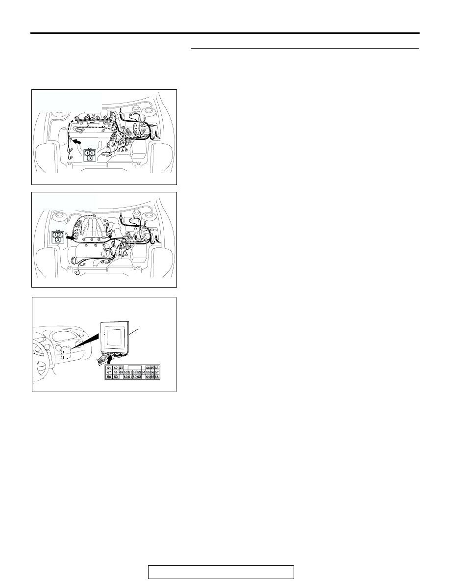
STEP 3. Check crankshaft position sensor connector B-20 
and PCM connector C-54 <2.4L Engine> or C-55 <3.0L 
Engine> for loose, corroded or damaged terminals, or 
terminals pushed back in the connector.
Q: Are the connectors and terminals in good condition?

YES : Go to Step 4.
NO :  Repair or replace the damaged components. Refer to 

GROUP 00E, Harness Connector Inspection 

P.00E-2

.

AC004926AC

CONNECTOR: B-20
<2.4L ENGINE>

B-20

AC004927AC

CONNECTOR: B-20
<3.0L ENGINE>

B-20

AC001657

CONNECTOR: C-54 <2.4L ENGINE> OR
C-55 <3.0L ENGINE>

PCM

BA

C-54 <2.4L ENGINE> OR C-55 <3.0L ENGINE>

AUTOMATIC TRANSAXLE DIAGNOSIS

TSB Revision

AUTOMATIC TRANSAXLE

23A-102

STEP 4. Using scan tool MB991958, check data list item 21: 
Crankshaft Position Sensor.

CAUTION

To prevent damage to scan tool MB991958, always turn the 
ignition switch to the "LOCK" (OFF) position before con-
necting or disconnecting scan tool MB991958.
(1) Connect scan tool MB991958 to the data link connector.
(2) With the gear selector lever in the "P" position, start the 

engine and run at idle.

(3) Set scan tool MB991958 to data reading mode for item 21: 

Crankshaft Position Sensor.

• When the accelerator pedal is not depressed (throttle 

valve is fully closed) the display on the scan tool 
MB991958 should be "600 to 900 r/min."

• With the accelerator pedal depressed, the engine speed 

display on the scan tool MB991958 should increase 
according to engine speed.

Q: Does the engine speed display increase according to 

engine speed when the accelerator pedal is depressed?
YES : 
It can be assumed that this malfunction is intermittent. 

Refer to GROUP 00, How to Use 
Troubleshooting/Inspection Service Points 

− How to 

Cope with Intermittent Malfunction 

P.00-6

.

NO :  Replace the PCM.

STEP 5. Check crankshaft position sensor connector B-20 
for loose, corroded or damaged terminals, or terminals 
pushed back in the connector.
Q: Are the connector and terminals in good condition?

YES : Go to Step 6.
NO :  Repair or replace the damaged components. Refer to 

GROUP 00E, Harness Connector Inspection 

P.00E-2

.

AC303127

AB

MB991911

16-PIN

MB991827

MB991824 

AC004926AC

CONNECTOR: B-20
<2.4L ENGINE>

B-20

AC004927AC

CONNECTOR: B-20
<3.0L ENGINE>

B-20

AUTOMATIC TRANSAXLE DIAGNOSIS

TSB Revision

AUTOMATIC TRANSAXLE

23A-103

STEP 6. Measure the sensor output voltage at crankshaft 
position sensor connector B-20.
(1) Disconnect connector B-20 and measure at the harness 

side.

(2) Turn the ignition switch to the "ON" position.

(3) Measure the voltage between terminal 2 and ground.

•  The voltage should measure between 4.9 and 5.1 volts.

(4) Turn the ignition switch to the "LOCK" (OFF) position.
Q: Is the measured voltage between 4.9 and 5.1 volts?

YES : Go to Step 12.
NO :  Go to Step 7.

AC004926AC

CONNECTOR: B-20
<2.4L ENGINE>

B-20

AC004927AC

CONNECTOR: B-20
<3.0L ENGINE>

B-20

ACX02114

B-20 HARNESS
CONNECTOR:
COMPONENT SIDE

AK

AUTOMATIC TRANSAXLE DIAGNOSIS

TSB Revision

AUTOMATIC TRANSAXLE

23A-104

STEP 7. Measure the sensor output voltage at PCM 
connector C-54 <2.4L Engine> or C-55 <3.0L Engine> by 
backprobing.
(1) Do not disconnect connector C-54 <2.4L Engine> or C-55 

<3.0L Engine>.

(2) Disconnect connector B-20 at the crankshaft position 

sensor.

(3) Turn the ignition switch to the "ON" position.

(4) Measure the voltage between terminal 45 and ground by 

backprobing.

• Voltage should measure between 4.9 and 5.1 volts.

(5) Turn the ignition switch to the "LOCK" (OFF) position.
Q: Is the measured voltage between 4.9 and 5.1 volts?

YES : Go to Step 8.
NO :  Go to Step 10.

STEP 8. Check PCM connector C-54 <2.4L Engine> or C-55 
<3.0L Engine> for loose, corroded or damaged terminals, 
or terminals pushed back in the connector.
Q: Are the connector and terminals in good condition?

YES : Go to Step 9.
NO :  Repair or replace the damaged components. Refer to 

GROUP 00E, Harness Connector Inspection 

P.00E-2

.

AC001657

CONNECTOR: C-54 <2.4L ENGINE> OR
C-55 <3.0L ENGINE>

PCM

BA

C-54 <2.4L ENGINE> OR C-55 <3.0L ENGINE>

AC001806 AN

C-54 <2.4L ENGINE> OR
C-55 <3.0L ENGINE>

HARNESS CONNECTOR:
HARNESS SIDE

AC001657

CONNECTOR: C-54 <2.4L ENGINE> OR
C-55 <3.0L ENGINE>

PCM

BA

C-54 <2.4L ENGINE> OR C-55 <3.0L ENGINE>


Content   ..  771  772  773  774   ..