Mitsubishi Eclipse. Manual - part 762
AUTOMATIC TRANSAXLE DIAGNOSIS
TSB Revision
AUTOMATIC TRANSAXLE
23A-57
STEP 5. Using scan tool MB991958, check data list item 11:
TP Sensor.
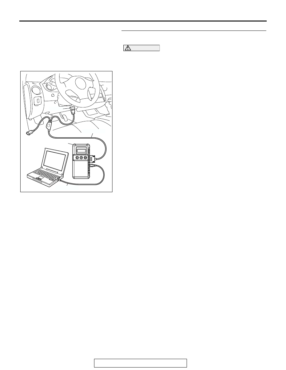
CAUTION
To prevent damage to scan tool MB991958, always turn the
ignition switch to the "LOCK" (OFF) position before con-
necting or disconnecting scan tool MB991958.
(1) Connect scan tool MB991958 to the data link connector.
(2) Turn the ignition switch to the "ON" position.
(3) Set scan tool MB991958 to data reading mode for item 11:
TP Sensor.
• With the throttle valve in the idle position, voltage should
measure between 535 and 735 mV.
• With the throttle valve in the full-open position, voltage
should measure between 4,500 and 5,500 mV.
(4) Turn the ignition switch to the "LOCK" (OFF) position.
Q: Is the sensor voltage between 535 and 735 mV at idle,
and between 4,500 and 5,500 mV in the full-open
position?
YES : It can be assumed that this malfunction is intermittent.
Refer to GROUP 00, How to Use
Troubleshooting/Inspection Service Points
− How to
Cope with Intermittent Malfunction
.
NO : Replace the PCM.
AC303127
AB
MB991911
16-PIN
MB991827
MB991824