Mitsubishi Eclipse. Manual - part 713


  Index      Mitsubishi     Mitsubishi Eclipse - service repair manual 2004 year


Search            


Content   ..  711  712  713  714   ..


Mitsubishi Eclipse. Manual - part 713


ENGINE ROLL STOPPER AND CENTERMEMBER

TSB Revision

POWER PLANT MOUNT

32-9

INSTALLATION SERVICE POINT

.

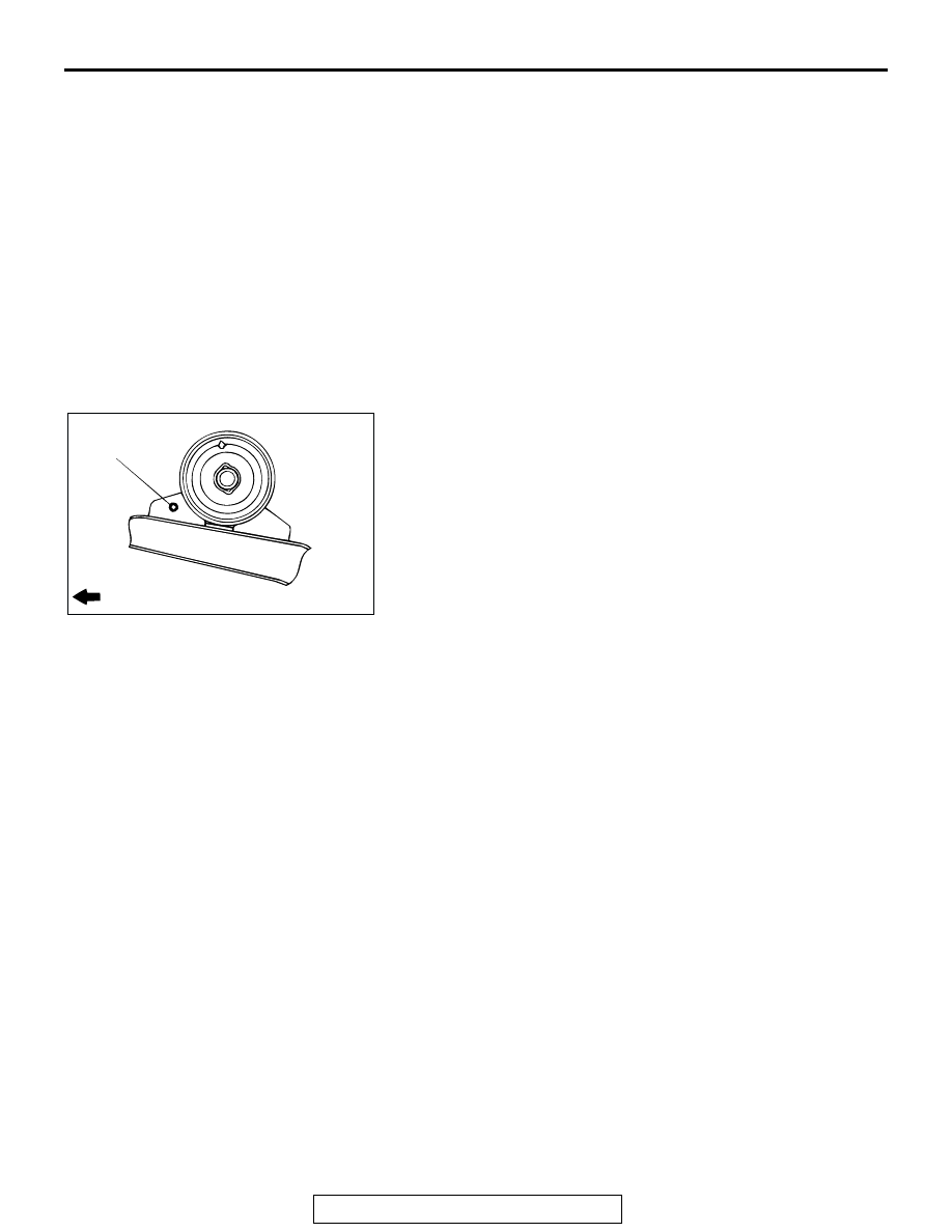
>>A<< FRONT ROLL STOPPER INSTALLATION
Install so that the hole in the front roll stopper is facing towards 
the front of the vehicle.

FRONT ROLL STOPPER, 
CENTERMEMBER REMOVAL 
STEPS

1.

TRANSAXLE AND FRONT ROLL 
STOPPER CONNECTING BOLT

2.

CENTERMEMBER MOUNTING 
BOLTS

3.

STOPPER

4.

CENTERMEMBER

>>A<<

5.

FRONT ROLL STOPPER

6.

COLLAR

7.

BUSHING (LOWER)

8.

BUSHING (UPPER)
REAR ROLL STOPPER 
REMOVAL STEPS

9.

TRANSAXLE AND REAR ROLL 
STOPPER CONNECTING BOLT

10. REAR ROLL STOPPER

FRONT ROLL STOPPER, 
CENTERMEMBER REMOVAL 
STEPS (Continued)

AC000304 AB

FRONT OF VEHICLE

HOLE

CROSSMEMBER

TSB Revision

POWER PLANT MOUNT

32-10

CROSSMEMBER

REMOVAL AND INSTALLATION

M1321003200186

CAUTION

*

: Indicates parts which should be temporarily tightened, and then fully tightened with the vehicle 

on the ground in the unladen condition.

• For vehicles with SRS, before removal of steering gear box, refer to GROUP 52B, center the front 

wheels and remove the ignition key. Failure to do so may damage the SRS clock spring and render 
the SRS system inoperative, risking serious injury.

Pre-removal Operation
• Power Steering Fluid Draining (Refer to GROUP 37A, 

On-vehicle Service 

− Fluid Replacement 

P.37A-17

 .)

• Centermember Removal (Refer to 

P.32-8

 .)

• Front Exhaust Pipe Removal (Refer to GROUP 15, 

Exhaust pipe and Main Muffler 

P.15-22

 <2.4L Engine>, 

P.15-24

 <3.0L Engine>.)

• Stabilizer Bar Removal (Refer to GROUP 33A, Stabilizer 

Bar 

P.33A-16

 .)

• Rear Roll Stopper Removal (Refer to 

P.32-8

 .)

Post-installation Operation
• Rear Roll Stopper Installation (Refer to 

P.32-8

 .)

• Stabilizer Bar Installation (Refer to GROUP 33A, Stabilizer 

Bar 

P.33A-16

 .)

• Front Exhaust Pipe Installation (Refer to GROUP 15, 

Exhaust Pipe and Main Muffle

P.15-22

 <2.4L Engine>, 

P.15-24

 <3.0L Engine>.)

• Centermember Installation (Refer to 

P.32-8

 .)

• Power Steering Fluid Supplying and Bleeding (Refer to 

GROUP 37A, On-vehicle Service 

− Fluid Replacement 

P.37A-17

 .)

• Steering Wheel Straight Ahead Position Checking.)

• Wheel Alignment Check and Adjustment (Refer to 

GROUP 33A, On-vehicle Service 

− Front Wheel Align-

ment Check and Adjustment 

P.33A-6

 .)

AC005142

6

7

8

9

10

4

11

5

4

2

1

108 ± 10 N·m
80 ± 7 ft-lb

108 ± 10 N·m*
80 ± 7 ft-lb*

88 ± 10 N·m
65 ± 7 ft-lb

74 ± 4 N·m
55 ± 3 ft-lb

81 ± 12 N·m
60 ± 9 ft-lb

AB

3

CROSSMEMBER

TSB Revision

POWER PLANT MOUNT

32-11

CROSSMEMBER BUSHING REPLACEMENT

M1321000900119

Required Special Tools:

• MB990828: Bushing Remover and Installer

• MB991045: Bushing Remover and Installer

Crossmember Bushings A and B

1. Apply soapy water to the contact surface of the bushing 

when press-fitted the bushing.

2. The bushing should be press-fitted so that the inner pipe 

projection is at the standard length.

Standard values

• <2.4L ENGINE>

• Bushing A: 9.0 ± 1.0 mm (0.35 ± 0.04 inch)

• Bushing B: 4.0 ± 1.0 mm (0.16 ± 0.04 inch)

• <3.0L ENGINE>

• Bushing A, B: 9.0 ± 1.0 mm (0.35 ± 0.04 inch)

REMOVAL STEPS

1.

STAY <2.4L ENGINE>

2.

LOWER ARM AND 
CROSSMEMBER 
CONNECTION

3.

LOWER ARM MOUNT BOLT

POWER STEERING GEAR BOX 
(REFER TO GROUP 37A, 
POWER STEERING GEAR BOX 

P.37A-26

 .)

4.

CROSSMEMBER MOUNTING 
NUT

5.

LOWER PLATE

6.

CROSSMEMBER

7.

STOPPER A

8.

STOPPER B

9.

BUSHING C

10. BUSHING A
11. BUSHING B

REMOVAL STEPS (Continued)

AC000306

REMOVAL

PRESS-FITTING

BOLT

WASHER

NUT

BASE

BASE

NUT

WASHER

BOLT

MB991045

AB

AC000307AB

<2.4L ENGINE>

BUSHING A

BUSHING B

INNER PIPE

INNER PIPE

AC000308

INNER PIPE

INNER PIPE

BUSHING A

BUSHING B

<3.0L ENGINE>

AB

CROSSMEMBER

TSB Revision

POWER PLANT MOUNT

32-12

Crossmember Bushing C

1. Use special tool MB990828 to drive out and press-fit the 

crossmember bushing C.

2. The bushing should be press-fitted so that the inner pipe 

projection is at the standard length.

Standard value (A): 4.0 

± 0.5 mm (0.16 ± 0.02 inch)

AC000309AB

REMOVAL

PRESS-FITTING

MB990828

AC000310

INNER PIPE

A

AB


Content   ..  711  712  713  714   ..