Mitsubishi Eclipse. Manual - part 702
AUTO-CRUISE CONTROL
TSB Revision
ENGINE AND EMISSION CONTROL
17-89
AUTO-CRUISE CONTROL SYSTEM COMPONENT
CHECK
M1172001700286
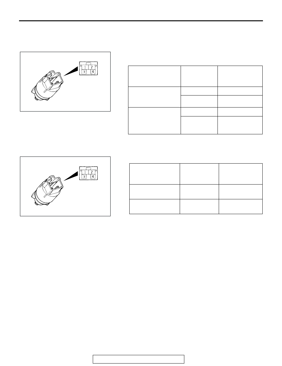
Stoplight Switch
1. Disconnect the connector.
2. Check for continuity between the terminals of the switch.
Clutch Pedal Position Switch
1. Disconnect the connector.
2. Check for continuity between the terminals of the switch.
Transmission Range Switch ("N" Position)
Refer to GROUP 23A, On-vehicle Service
− Essential Service
.
Throttle Position Sensor
For 2.4L engine, refer to GROUP 13A, On-vehicle Service
−
Throttle Position Sensor Check
.
For 3.0L engine, refer to GROUP 13B, On-vehicle Service
−
Throttle Position Sensor Check
.
MEASUREMENT
CONDITION
TERMINAL
CONNECTOR
OF TESTER
SPECIFIED
CONDITION
When brake pedal is
depressed. (for
stoplight circuit)
1
− 2
Less than 2 ohms
3
− 4
Open circuit
When brake pedal is
not depressed. (for
auto-cruise control
circuit)
1
− 2
Open circuit
3
− 4
Less than 2 ohms
ACX01180 AB
MEASUREMENT
CONDITION
TERMINAL
CONNECTOR
OF TESTER
SPECIFIED
CONDITION
When clutch pedal is
depressed.
1
− 2
Less than 2 ohms
When clutch pedal is
not depressed.
1
− 2
Open circuit
ACX01180 AB