Mitsubishi Eclipse. Manual - part 608


  Index      Mitsubishi     Mitsubishi Eclipse - service repair manual 2004 year


Search            


Content   ..  606  607  608  609   ..


Mitsubishi Eclipse. Manual - part 608


MULTIPORT FUEL INJECTION (MFI) DIAGNOSIS

TSB Revision

MULTIPORT FUEL INJECTION (MFI) <3.0L>

13B-975

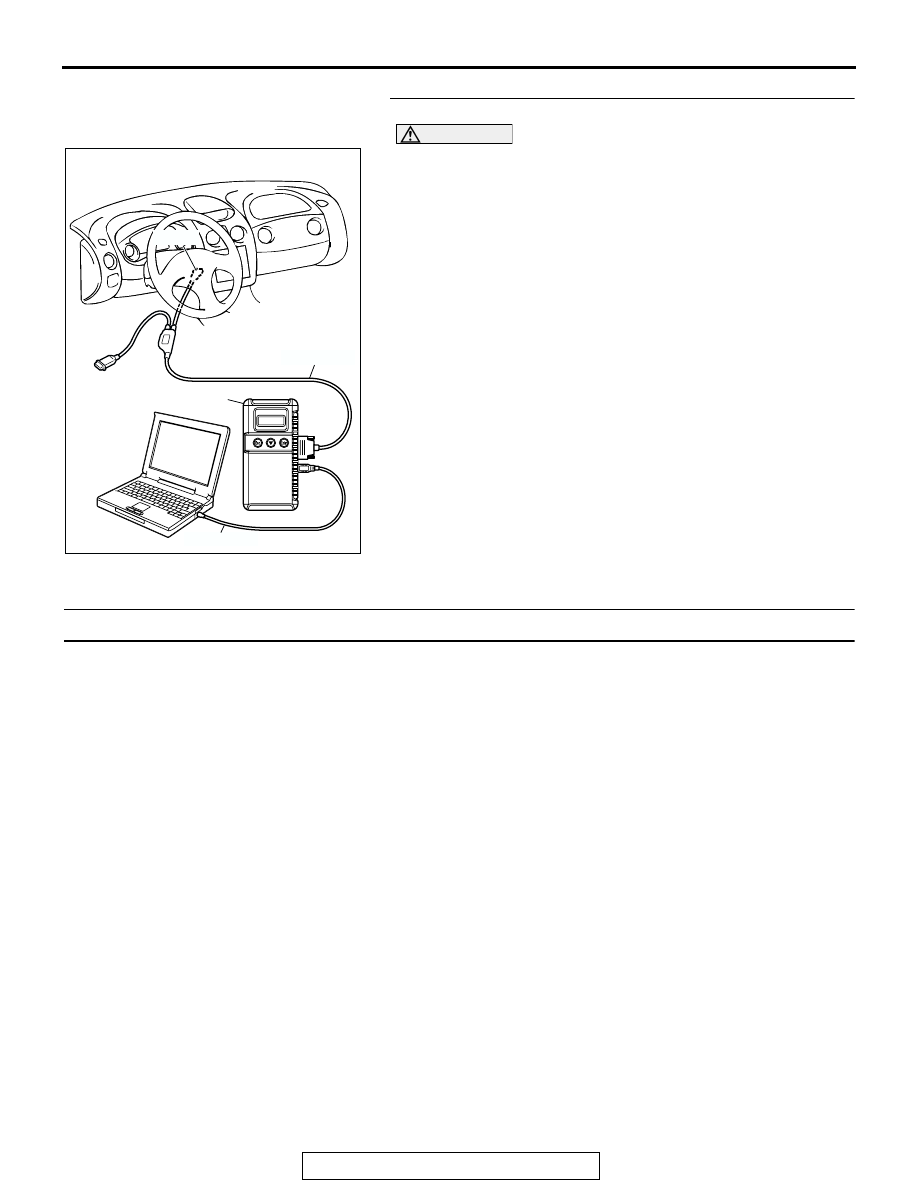
STEP 3. Using scan tool MB991958, check data list.

CAUTION

To prevent damage to scan tool MB991958, always turn the 
ignition switch to the "LOCK" (OFF) position before con-
necting or disconnecting scan tool MB991958.
(1) Connect scan tool MB991958 to the data link connector.
(2) Turn the ignition switch to the "ON" position.
(3) Check the following items in the data list. Refer to, Data List 

Reference Table 

P.13B-1062

.

a. Item 14: Throttle Position Sensor.

(4) Turn the ignition switch to the "LOCK" (OFF) position.
Q: Is the sensor operating properly?

YES : Refer to, Clean the throttle valve area 

P.13B-1102

.

NO :  Repair or replace. Then confirm that the malfunction 

symptom is eliminated.

INSPECTION PROCEDURE 18: Poor acceleration.

.

COMMENT

• Defective ignition system, abnormal air/fuel ratio, 

poor compression pressure, etc. are suspected.

.

TROUBLESHOOTING HINTS (The most likely 
causes for this case: )

• Malfunction of the ignition system.

• Malfunction of air/fuel ratio control system.

• Malfunction of the fuel supply system.

• Poor compression pressure.

• Clogged exhaust system.

DIAGNOSIS

Required Special Tools:

• MB991958: Scan Tool (MUT-III Sub Assembly)

• MB991824: V.C.I.

• MB991827: USB Cable

• MB991911: Main Harness B

AK300810

AB

MB991911

16-PIN

MB991827

MB991824 

MULTIPORT FUEL INJECTION (MFI) DIAGNOSIS

TSB Revision

MULTIPORT FUEL INJECTION (MFI) <3.0L>

13B-976

STEP 1. Using scan tool MB991958, read the diagnostic 
trouble code (DTC).

CAUTION

To prevent damage to scan tool MB991958, always turn the 
ignition switch to the "LOCK" (OFF) position before con-
necting or disconnecting scan tool MB991958.
(1) Connect scan tool MB991958 to the data link connector.
(2) Turn the ignition switch to the "ON" position.
(3) Read the DTC.
(4) Turn the ignition switch to the "LOCK" (OFF) position.
Q: Is DTC set?

YES : Refer to, Diagnostic Trouble Code Chart 

P.13B-23

.

NO :  Go to Step 2.

STEP 2. Using scan tool MB991958, check actuator test 
items 01, 02, 03, 04, 05, 06: Injector.
(1) Turn the ignition switch to the "ON" position.
(2) Check following items in the actuator test. Refer to, Actuator 

Test Table 

P.13B-1078

.

a. Item 01, 02, 03, 04, 05, 06: Injector.

(3) Turn the ignition switch to the "LOCK" (OFF) position.
Q: Is the actuator operating properly?

YES : Go to Step 3.
NO :  Refer to, DTC P0201, P0203, P0205 

− Injector Circuit 

P.13B-510

, DTC P0202, P0204, P0206 

− Injector 

Circuit 

P.13B-521

.

AK300810

AB

MB991911

16-PIN

MB991827

MB991824 

AK300810

AB

MB991911

16-PIN

MB991827

MB991824 

MULTIPORT FUEL INJECTION (MFI) DIAGNOSIS

TSB Revision

MULTIPORT FUEL INJECTION (MFI) <3.0L>

13B-977

STEP 3. Check the ignition timing.
Refer to GROUP 11C, On-vehicle Service 

− Ignition Timing 

Check 

P.11C-7

.

Q: Is the ignition timing normal?

YES : Go to Step 4.
NO :  Check that the crankshaft position sensor and timing 

belt cover are in the correct position. Then confirm 
that the malfunction symptom is eliminated.

STEP 4. Using scan tool MB991958, check data list.

CAUTION

To prevent damage to scan tool MB991958, always turn the 
ignition switch to the "LOCK" (OFF) position before con-
necting or disconnecting scan tool MB991958.
(1) Connect scan tool MB991958 to the data link connector.
(2) Turn the ignition switch to the "ON" position.
(3) Check the following items in the data list. Refer to, Data List 

Reference Table 

P.13B-1062

.

a. Item 13: Intake Air Temperature Sensor.
b. Item 25: Barometric Pressure Sensor.

c. Item 21: Engine Coolant Temperature Sensor.

d. Item 14: Throttle Position Sensor.
e. Item 69: Right Bank Heated Oxygen Sensor (rear).

f. Item 39: Right Bank Heated Oxygen Sensor (front).

g. Item 59: Left Bank Heated Oxygen Sensor (rear).
h. Item 11: Left Bank Heated Oxygen Sensor (front).

(4) Turn the ignition switch to the "LOCK" (OFF) position.
Q: Are they operating properly?

YES : Go to Step 5.
NO :  Repair or replace. Then confirm that the malfunction 

symptom is eliminated.

AK300810

AB

MB991911

16-PIN

MB991827

MB991824 

MULTIPORT FUEL INJECTION (MFI) DIAGNOSIS

TSB Revision

MULTIPORT FUEL INJECTION (MFI) <3.0L>

13B-978

STEP 5. Using scan tool MB991958, check actuator test.
(1) Turn the ignition switch to the "ON" position.
(2) Check the following items in the actuator test. Refer to, 

Actuator Test Reference Table 

P.13B-1078

.

a. Item 10: EGR Vacuum Regulator Solenoid Valve.

(3) Turn the ignition switch to the "LOCK" (OFF) position.
Q: Are they operating properly?

YES : Go to Step 6.
NO :  Repair or replace. Then confirm that the malfunction 

symptom is eliminated.

STEP 6. Using scan tool MB991958, check data list.
(1) Turn the ignition switch to the "ON" position.
(2) Check the following items of data list. Refer to, Data List 

Reference Table 

P.13B-1062

.

a. Item 39: Right Bank Heated Oxygen Sensor (front).
b. Item 11: Left Bank Heated Oxygen Sensor (front).

• Voltage should fluctuate between 0 − 0.4 volt and 0.6 − 

1.0 volt while idling after the engine has been warmed.

(3) Turn the ignition switch to the "LOCK" (OFF) position.
Q: Is the sensor operating properly?

YES : Go to Step 8.
NO :  Go to Step 7.

AK300810

AB

MB991911

16-PIN

MB991827

MB991824 

AK300810

AB

MB991911

16-PIN

MB991827

MB991824 


Content   ..  606  607  608  609   ..