Mitsubishi Eclipse. Manual - part 559


  Index      Mitsubishi     Mitsubishi Eclipse - service repair manual 2004 year


Search            


Content   ..  557  558  559  560   ..


Mitsubishi Eclipse. Manual - part 559


MULTIPORT FUEL INJECTION (MFI) DIAGNOSIS

TSB Revision

MULTIPORT FUEL INJECTION (MFI) <3.0L>

13B-779

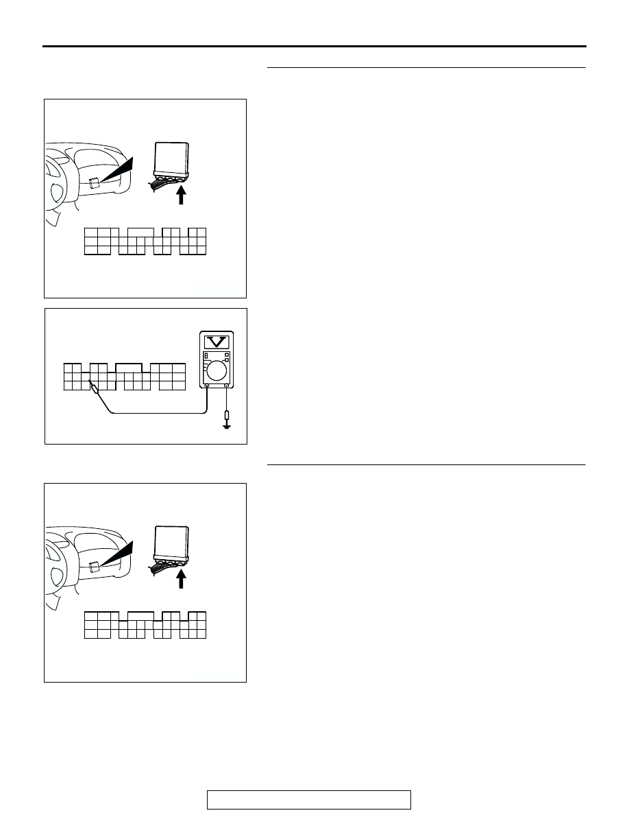
STEP 6. Check the sensor supply voltage at ECM 
connector C-62 by backprobing.
(1) Do not disconnect the ECM connector C-62.
(2) Disconnect the vehicle speed sensor connector B-39.
(3) Turn the ignition switch to the "ON" position.

(4) Measure the voltage between terminal No. 80 and ground 

by backprobing.

• Voltage should be between 4.8 and 5.2 volts.

(5) Turn the ignition switch to the "LOCK" (OFF) position.
Q: Is the measured voltage between 4.8 and 5.2 volts?

YES : Go to Step 7.
NO :  Replace the ECM. Then go to Step 17.

STEP 7. Check connector C-62 at ECM for damage.
Q: Is the connector in good condition?

YES : Check connector B-36 at intermediate connector for 

damage, and repair or replace as required. Refer to 
GROUP 00E, Harness Connector Inspection 

P.00E-2

. If intermediate connector is in good 

condition, repair harness wire between vehicle speed 
sensor connector B-39 (terminal No. 3) and ECM 
connector C-62 (terminal No. 80) because of open 
circuit. Then go to Step 17.

NO :  Repair or replace it. Refer to GROUP 00E, Harness 

Connector Inspection 

P.00E-2

. Then go to Step 17.

AK300445

80

87

81

94

85

82

84

93

86

98

99

74

92

73

83

88

91

95

97 96

100

89

78

71

90

76

77

75

72
79

CONNECTOR: C-62 <M/T>

C-62 (GR)

AB

HARNESS CONNECTOR:
COMPONENT SIDE

AK000258

71 72

73 74

78

80 81

79

82 83 84 85 86 87 88 89

75 76

91 92 93

94 95

96

98

99

97

AK000258AE

C-62 HARNESS 
CONNECTOR: 
HARNESS SIDE

77

90

100

AK300445

80

87

81

94

85

82

84

93

86

98

99

74

92

73

83

88

91

95

97 96

100

89

78

71

90

76

77

75

72
79

CONNECTOR: C-62 <M/T>

C-62 (GR)

AB

HARNESS CONNECTOR:
COMPONENT SIDE

MULTIPORT FUEL INJECTION (MFI) DIAGNOSIS

TSB Revision

MULTIPORT FUEL INJECTION (MFI) <3.0L>

13B-780

STEP 8. Check connector B-39 at vehicle speed sensor for 
damage.
Q: Is the connector in good condition?

YES : Go to Step 9.
NO :  Repair or replace it. Refer to GROUP 00E, Harness 

Connector Inspection 

P.00E-2

. Then go to Step 17.

STEP 9. Check the power supply voltage at vehicle speed 
sensor harness side connector B-39.
(1) Disconnect the connector B-39 and measure at the harness 

side.

(2) Turn the ignition switch to the "ON" position.

(3) Measure the voltage between terminal No. 1 and ground.

• Voltage should be battery positive voltage.

(4) Turn the ignition switch to the "LOCK" (OFF) position.
Q: Is battery positive voltage (approximately 12 volts) 

present?
YES : 
Go to Step 10.
NO :  Check connectors B-36, C-28, C-78, C-112 and C-111 

at intermediate connector for damage, and repair or 
replace as required. Refer to GROUP 00E, Harness 
Connector Inspection 

P.00E-2

. If intermediate 

connectors are in good condition, repair harness wire 
between ignition switch connector C-87 (terminal No. 
2) and vehicle speed sensor connector B-39 (terminal 
No. 1) because of open circuit or short circuit to 
ground. Then go to Step 17.

AK300425

1

2

3

B-39 (B)

AB

CONNECTOR: B-39

HARNESS CONNECTOR:
COMPONENT SIDE

AK300425

1

2

3

B-39 (B)

AB

CONNECTOR: B-39

HARNESS CONNECTOR:
COMPONENT SIDE

AKX01425AI

1

2

3

B-39 HARNESS 
CONNECTOR: 
COMPONENT SIDE

MULTIPORT FUEL INJECTION (MFI) DIAGNOSIS

TSB Revision

MULTIPORT FUEL INJECTION (MFI) <3.0L>

13B-781

STEP 10. Check the continuity at vehicle speed sensor 
harness side connector B-39.
(1) Disconnect the connector B-39 and measure at the harness 

side.

(2) Check for the continuity between terminal No. 2 and 

ground.

• Should be less than 2 ohms.

Q: Is the continuity normal?

YES : Go to Step 11.
NO :  Check connector B-36 at intermediate connector for 

damage, and repair or replace as required. Refer to 
GROUP 00E, Harness Connector Inspection 

P.00E-2

. If intermediate connector is in good 

condition, repair harness wire between vehicle speed 
sensor connector B-39 (terminal No. 2) and ground 
because of open circuit or harness damage. Then go 
to Step 17.

AK300425

1

2

3

B-39 (B)

AB

CONNECTOR: B-39

HARNESS CONNECTOR:
COMPONENT SIDE

AKX01426

3 2 1

B-39 HARNESS 
CONNECTOR: 
COMPONENT SIDE

AR

MULTIPORT FUEL INJECTION (MFI) DIAGNOSIS

TSB Revision

MULTIPORT FUEL INJECTION (MFI) <3.0L>

13B-782

STEP 11. Check the sensor supply voltage at vehicle speed 
sensor harness side connector B-39.
(1) Disconnect the vehicle speed sensor connector B-39 and 

measure at the harness side.

(2) Disconnect the combination meter connector and 

auto-cruise control-ECU connector.

(3) Turn the ignition switch to the "ON" position.

(4) Measure the voltage between terminal No. 3 and ground.

• Voltage should be between 4.8 and 5.2 volts.

(5) Turn the ignition switch to the "LOCK" (OFF) position.
Q: Is the measured voltage between 4.8 and 5.2 volts?

YES : Go to Step 12.
NO :  Check connector B-36 at intermediate connector for 

damage, and repair or replace as required. Refer to 
GROUP 00E, Harness Connector Inspection 

P.00E-2

. If intermediate connector is in good 

condition, repair harness wire between vehicle speed 
sensor connector B-39 (terminal No. 3) and ECM 
connector C-62 (terminal No. 80) because of short 
circuit to ground or harness damage. Then go to Step 
17.

STEP 12. Check the vehicle speed sensor.
Refer to GROUP 54A, Combination Metres Assembly and 
Vehicle Speed Sensor 

− Combination Metres Assembly and 

Vehicle Speed Sensor 

− Inspection 

P.54A-113

.

Q: Is the vehicle speed sensor normal?

YES : Go to Step 13.
NO :  Replace the vehicle speed sensor. Then go to Step 

17.

STEP 13. Check connector C-62 at ECM for damage.
Q: Is the connector in good condition?

YES : Go to Step 14.
NO :  Repair or replace it. Refer to GROUP 00E, Harness 

Connector Inspection 

P.00E-2

. Then go to Step 17.

AK300425

1

2

3

B-39 (B)

AB

CONNECTOR: B-39

HARNESS CONNECTOR:
COMPONENT SIDE

AKX01427

3 2 1

AR

B-39 HARNESS 
CONNECTOR: 
COMPONENT SIDE

AK300425

1

2

3

B-39 (B)

AB

CONNECTOR: B-39

HARNESS CONNECTOR:
COMPONENT SIDE


Content   ..  557  558  559  560   ..