Mitsubishi Eclipse. Manual - part 500


  Index      Mitsubishi     Mitsubishi Eclipse - service repair manual 2004 year


Search            


Content   ..  498  499  500  501   ..


Mitsubishi Eclipse. Manual - part 500


MULTIPORT FUEL INJECTION (MFI) DIAGNOSIS

TSB Revision

MULTIPORT FUEL INJECTION (MFI) <3.0L>

13B-543

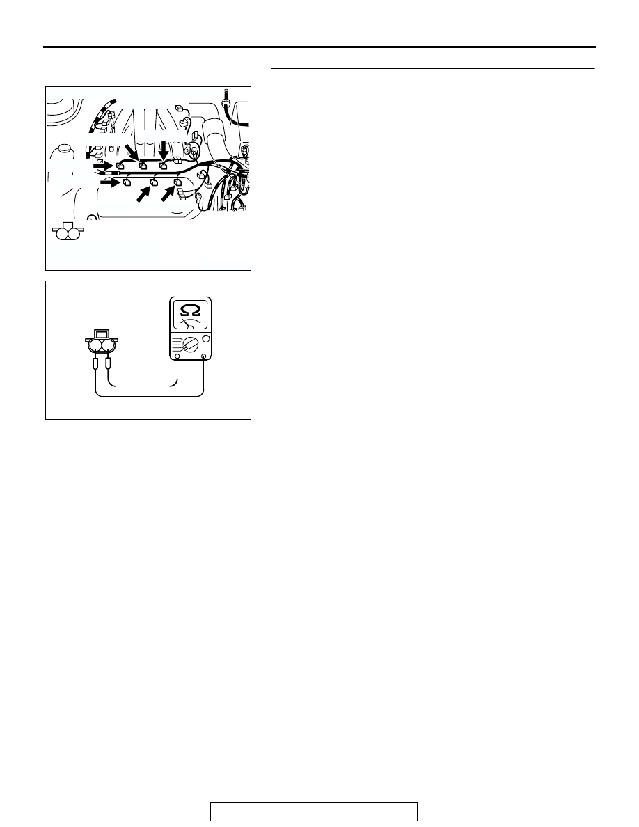
STEP 3. Check the injector.
(1) Disconnect the injector connector B-01 <No. 1 cylinder>, 

B-02 <No.  2 cylinder>, B-05 <No. 3 cylinder>, B-06 <No. 4 
cylinder>, B-26 <No. 5 cylinder>, B-25 <No. 6 cylinder>.

(2) Measure the resistance between injector side connector 

terminal No. 1 and No. 2.

Standard value: 13 

 16 ohms [at 20°C (68°F)]

Q: Is the resistance between 13 and 16 ohms?

YES : Go to Step 4.
NO :  Replace the injector. Then go to Step 9.

AK300754

1

2

CONNECTORS: B-01, B-02, B-05, B-06, 
                            B-25, B-26

AB

B-01 (GR)

B-05 (GR)

B-26 (GR)

B-02 (GR)

B-06 (GR)

B-25 (GR)

HARNESS CONNECTOR:
COMPONENT SIDE

AK000241

INJECTOR SIDE
CONNECTOR

1 2

AB

MULTIPORT FUEL INJECTION (MFI) DIAGNOSIS

TSB Revision

MULTIPORT FUEL INJECTION (MFI) <3.0L>

13B-544

STEP 4. Check connector at injector and injector 
intermediate connector for damage.

a. Check the connector B-01 at injector and connector B-48 at 

injector intermediate connector when checking No. 1 cylin-
der.

b. Check the connector B-02 at injector when checking No. 2 

cylinder.

c. Check the connector B-05 at injector and connector B-48 at 

injector intermediate connector when checking No. 3 cylin-
der.

d. Check the connector B-06 at injector when checking No. 4 

cylinder.

e. Check the connector B-26 at injector and connector B-48 at 

injector intermediate connector when checking No. 5 cylin-
der.

f. Check the connector B-25 at injector when checking No. 6 

cylinder.

Q: Is the connector in good condition?

YES : Go to Step 5.
NO :  Repair or replace the injector. Refer to GROUP 00E, 

Harness Connector Inspection 

P.00E-2

. Then go to 

Step 9.

AK300754

1

2

CONNECTORS: B-01, B-02, B-05, B-06, 
                            B-25, B-26

AB

B-01 (GR)

B-05 (GR)

B-26 (GR)

B-02 (GR)

B-06 (GR)

B-25 (GR)

HARNESS CONNECTOR:
COMPONENT SIDE

AK300751

1

2

3

4

CONNECTOR: B-48

AB

B-48 (B)

HARNESS CONNECTOR:
COMPONENT SIDE

MULTIPORT FUEL INJECTION (MFI) DIAGNOSIS

TSB Revision

MULTIPORT FUEL INJECTION (MFI) <3.0L>

13B-545

STEP 5. Check connector C-51 at ECM <M/T> or connector 
C-52 at PCM <A/T> for damage.
Q: Is the connector in good condition?

YES : Go to Step 6.
NO :  Repair or replace it. Refer to GROUP 00E, Harness 

Connector Inspection 

P.00E-2

. Then go to Step 9.

AK300458

2

3

4

5

6

7

8

9

11

12

13

14

15

16

17

18

19

20

30

21

22

23

24

25

26

27

28

29

31

32

33

34

35

1

10

CONNECTOR: C-52 <A/T>

C-52 (GR)

AB

HARNESS CONNECTOR:
COMPONENT SIDE

AK300443

2

3

4

5

6

7

8

9

11

12

13

14

15

16

17

18

19

20

30

21

22

23

24

25

26

27

28

29

31

32

33

34

35

1

10

CONNECTOR: C-51 <M/T>

C-51 (GR)

AB

HARNESS CONNECTOR:
COMPONENT SIDE

MULTIPORT FUEL INJECTION (MFI) DIAGNOSIS

TSB Revision

MULTIPORT FUEL INJECTION (MFI) <3.0L>

13B-546

STEP 6. Check for harness damage between injector 
connector and ECM connector <M/T> or PCM connector 
<A/T>.

a. Check the harness wire between injector connector B-01 

(terminal No. 2) and ECM connector C-51 (terminal No. 1) 
<M/T> or PCM connector C-52 (terminal No. 1) <A/T> when 
checking No. 1 cylinder.

b. Check the harness wire between injector connector B-02 

(terminal No. 2) and ECM connector C-51 (terminal No. 9) 
<M/T> or PCM connector C-52 (terminal No. 9) <A/T> when 
checking No. 2 cylinder.

c. Check the harness wire between injector connector B-05 

(terminal No. 2) and ECM connector C-51 (terminal No. 24) 
<M/T> or PCM connector C-52 (terminal No. 24) <A/T> 
when checking No. 3 cylinder.

d. Check the harness wire between injector connector B-06 

(terminal No. 2) and ECM connector C-51 (terminal No. 2) 
<M/T> or PCM connector C-52 (terminal No. 2) <A/T> when 
checking No. 4 cylinder.

e. Check the harness wire between injector connector B-26 

(terminal No. 2) and ECM connector C-51 (terminal No. 10) 
<M/T> or PCM connector C-52 (terminal No. 10) <A/T> 
when checking No. 5 cylinder.

f. Check the harness wire between injector connector B-25 

(terminal No. 2) and ECM connector C-51 (terminal No. 25) 
<M/T> or PCM connector C-52 (terminal No. 25) <A/T> 
when checking No. 6 cylinder.

Q: Is the harness wire in good condition?

YES : Go to Step 7.
NO :  Repair it. Then go to Step 9.

AK300754

1

2

CONNECTORS: B-01, B-02, B-05, B-06, 
                            B-25, B-26

AB

B-01 (GR)

B-05 (GR)

B-26 (GR)

B-02 (GR)

B-06 (GR)

B-25 (GR)

HARNESS CONNECTOR:
COMPONENT SIDE

AK300458

2

3

4

5

6

7

8

9

11

12

13

14

15

16

17

18

19

20

30

21

22

23

24

25

26

27

28

29

31

32

33

34

35

1

10

CONNECTOR: C-52 <A/T>

C-52 (GR)

AB

HARNESS CONNECTOR:
COMPONENT SIDE

AK300443

2

3

4

5

6

7

8

9

11

12

13

14

15

16

17

18

19

20

30

21

22

23

24

25

26

27

28

29

31

32

33

34

35

1

10

CONNECTOR: C-51 <M/T>

C-51 (GR)

AB

HARNESS CONNECTOR:
COMPONENT SIDE


Content   ..  498  499  500  501   ..