Mitsubishi Eclipse. Manual - part 492
MULTIPORT FUEL INJECTION (MFI) DIAGNOSIS
TSB Revision
MULTIPORT FUEL INJECTION (MFI) <3.0L>
13B-511
.
CIRCUIT OPERATION
• The injector power is supplied from the MFI relay
(terminal No. 4).
• The ECM <M/T> or PCM <A/T> controls the
injector by turning the power transistor in the
ECM <M/T> or PCM <A/T> "ON" and "OFF".
.
TECHNICAL DESCRIPTION
• The amount of fuel injected by the injector is con-
trolled by the amount of continuity time the coil is
grounded by the ECM <M/T> or PCM <A/T>.
• A surge voltage is generated when the injectors
are driven and the current flowing to the injector
coil is shut off.
• The ECM <M/T> or PCM <A/T> checks this
surge voltage.
.
DESCRIPTIONS OF MONITOR METHODS
Off-surge does not occur after injector is operated.
.
MONITOR EXECUTION
Continuous
.
MONITOR EXECUTION CONDITIONS (Other
monitor and Sensor)
Other Monitor (There is no temporary DTC stored
in memory for the item monitored below)
• Not applicable
Sensor (The sensor below is determined to be
normal)
• Not applicable
.
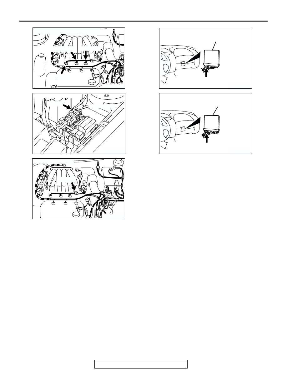
AK300086
CONNECTORS: B-01, B-05, B-26
AB
B-05 (GR)
B-26 (GR)
B-01 (GR)
AK300121
MFI RELAY
CONNECTOR: A-18X
AB
A-18X
AK300085
CONNECTOR: B-48
AB
B-48 (B)
AK300244
CONNECTOR: C-52 <A/T>
AC
PCM
C-52 (GR)
AK300091
CONNECTOR: C-51 <M/T>
ECM
AF
C-51 (GR)