Mitsubishi Eclipse. Manual - part 484


  Index      Mitsubishi     Mitsubishi Eclipse - service repair manual 2004 year


Search            


Content   ..  482  483  484  485   ..


Mitsubishi Eclipse. Manual - part 484


MULTIPORT FUEL INJECTION (MFI) DIAGNOSIS

TSB Revision

MULTIPORT FUEL INJECTION (MFI) <3.0L>

13B-479

OBD-ll DRIVE CYCLE PATTERN
Refer to Diagnostic Function 

− OBD-ll Drive Cycle − 

Procedure 6 

− Other Monitor 

P.13B-7

.

.

TROUBLESHOOTING HINTS (The most likely 
causes for this code to be set are: )

• Fuel tank temperature sensor failed.

• Open or shorted fuel tank temperature sensor cir-

cuit harness damage, or connector damage.

• ECM failed. <M/T>

• PCM failed. <A/T>

NOTE: A diagnostic trouble code (DTC) could be 
output if the engine coolant is changed as indicated 
below. Because this is not a failure, the DTC must be 
erased.
Make sure to test drive the vehicle in accordance 
with the drive cycle pattern in order to verify that a 
DTC will not be output.

.

The engine and the radiator have been flushed 
repeatedly when the engine coolant temperature 
was high (or the fuel tank temperature was high).

DIAGNOSIS

Required Special Tools:

• MB991958: Scan Tool (MUT-III Sub Assembly)

• MB991824: V.C.I.

• MB991827: USB Cable

• MB991911: Main Harness B

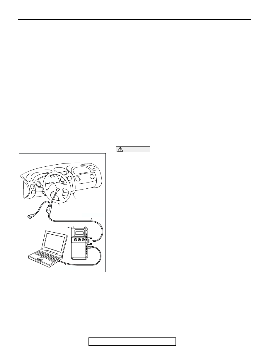
STEP 1. Using scan tool MB991958, check data list item 
4A: Fuel Tank Temperature Sensor.

CAUTION

To prevent damage to scan tool MB991958, always turn the 
ignition switch to the "LOCK" (OFF) position before con-
necting or disconnecting scan tool MB991958.
(1) Connect scan tool MB991958 to the data link connector.
(2) Turn the ignition switch to the "ON" position.
(3) Set scan tool MB991958 to the data reading mode for item 

4A, Fuel Tank Temperature Sensor.

• Approximately the same as the ambient air temperature 

when the engine is cooled.

(4) Turn the ignition switch to the "LOCK" (OFF) position.
Q: Is the sensor operating properly?

YES : It can be assumed that this malfunction is intermittent. 

Refer to GROUP 00, How to Use Troubleshooting/ 
Inspection Service Points 

P.00-6

.

NO :  Go to Step 2.

AK300810

AB

MB991911

16-PIN

MB991827

MB991824 

MULTIPORT FUEL INJECTION (MFI) DIAGNOSIS

TSB Revision

MULTIPORT FUEL INJECTION (MFI) <3.0L>

13B-480

STEP 2. Check connector D-17 at the fuel tank temperature 
sensor for damage.
Q: Is the connector in good condition?

YES : Go to Step 3.
NO :  Repair or replace it. Refer to GROUP 00E, Harness 

Connector Inspection 

P.00E-2

. Then go to Step 12.

STEP 3. Check the fuel tank temperature sensor.
(1) Disconnect the fuel tank temperature sensor connector 

D-17

(2) Measure the resistance between terminal No. 1 and No. 3 

of the fuel tank temperature sensor.

Standard value:

0.5 

 12.0 k

Q: Is the resistance between 0.5 and 12.0 k

?

YES : Go to Step 4.
NO :  Replace the fuel tank temperature sensor. Then go to 

Step 12.

AK300453

1

2

3

4

5

D-17 (GR)

AB

CONNECTOR: D-17

HARNESS CONNECTOR:
COMPONENT SIDE

AK300453

1

2

3

4

5

D-17 (GR)

AB

CONNECTOR: D-17

HARNESS CONNECTOR:
COMPONENT SIDE

AK101374

1 2 3

4 5

AB

1 2 3

4 5

FUEL TEMPERATURE SENSOR 
SIDE CONNECTOR

MULTIPORT FUEL INJECTION (MFI) DIAGNOSIS

TSB Revision

MULTIPORT FUEL INJECTION (MFI) <3.0L>

13B-481

STEP 4. Check the continuity at fuel tank temperature 
sensor harness side connector D-17.
(1) Disconnect the connector D-17 and measure at the harness 

side.

(2) Check for the continuity between terminal No. 1 and 

ground.

• Should be less than 2 ohms.

Q: Is the continuity normal?

YES : Go to Step 5.
NO :  Repair harness wire between fuel tank temperature 

sensor connector D-17 (terminal No. 1) and ground 
because of open circuit or harness damage. Then go 
to Step 12.

STEP 5. Check the sensor supply voltage at fuel tank 
temperature sensor harness side connector D-17.
(1) Disconnect the connector D-17 and measure at the harness 

side.

(2) Turn the ignition switch to the "ON" position.

(3) Measure the voltage between (terminal No. 3) and ground.

• Voltage should be between 4.5 and 4.9 volts

(4) Turn the ignition switch to the "LOCK" (OFF) position.
Q: Is the measured voltage between 4.5 and 4.9 volts?

YES : Go to Step 6.
NO :  Go to Step 10.

AK300453

1

2

3

4

5

D-17 (GR)

AB

CONNECTOR: D-17

HARNESS CONNECTOR:
COMPONENT SIDE

AK101375

1

2

3

4

5

AE

1

2

3

4

5

D-17 HERNESS
 CONNECTOR: 
COMPONENT SIDE

AK300453

1

2

3

4

5

D-17 (GR)

AB

CONNECTOR: D-17

HARNESS CONNECTOR:
COMPONENT SIDE

AK101376

1

2

3

4

5

AE

1

2

3

4

5

D-17 HERNESS 
CONNECTOR: 
COMPONENT SIDE

MULTIPORT FUEL INJECTION (MFI) DIAGNOSIS

TSB Revision

MULTIPORT FUEL INJECTION (MFI) <3.0L>

13B-482

STEP 6. Check the sensor supply voltage at ECM 
connector C-62 <M/T> or PCM connector C-55 <A/T> by 
backprobing.
(1) Do not disconnect the ECM connector C-62 <M/T> or PCM 

connector C-55 <A/T>.

(2) Turn the ignition switch to the "ON" position.

AK300462

42

43

48

49

50

51

52

53

54

55

56

57

46 45 44

58

59

60

61

62

63

64

65

66

47

41

CONNECTOR: C-55 <A/T>

C-55 (GR)

AB

HARNESS CONNECTOR:
COMPONENT SIDE

AK300445

80

87

81

94

85

82

84

93

86

98

99

74

92

73

83

88

91

95

97 96

100

89

78

71

90

76

77

75

72
79

CONNECTOR: C-62 <M/T>

C-62 (GR)

AB

HARNESS CONNECTOR:
COMPONENT SIDE


Content   ..  482  483  484  485   ..