Mitsubishi Eclipse. Manual - part 479


  Index      Mitsubishi     Mitsubishi Eclipse - service repair manual 2004 year


Search            


Content   ..  477  478  479  480   ..


Mitsubishi Eclipse. Manual - part 479


MULTIPORT FUEL INJECTION (MFI) DIAGNOSIS

TSB Revision

MULTIPORT FUEL INJECTION (MFI) <3.0L>

13B-459

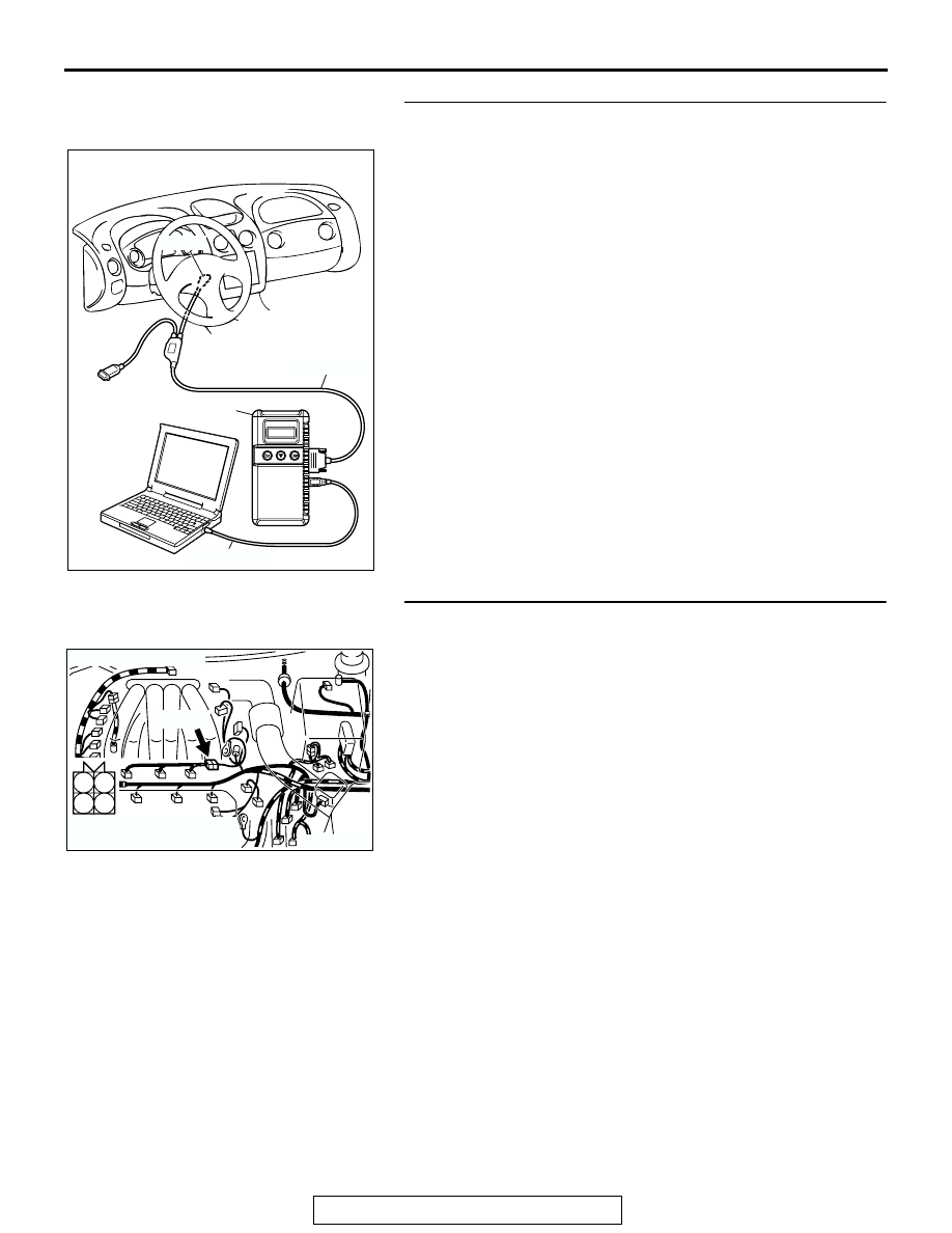
STEP 4. Using scan tool MB991958, check data list item 25: 
Barometric Pressure Sensor.
(1) Turn the ignition switch to the "ON" position.
(2) Set scan tool MB991958 to the data reading mode for item 

25, Barometric Pressure Sensor.

• When altitude is 0 m (0 foot), 101 kPa (29.8 in.Hg).

• When altitude is 600 m (1,969 feet), 95 kPa (28.1 in.Hg).

• When altitude is 1,200 m (3,937 feet), 88 kPa (26.0 

in.Hg).

• When altitude is 1,800 m (5,906 feet), 81 kPa (23.9 

in.Hg).

(3) Turn the ignition switch to the "LOCK" (OFF) position.
Q: Is the sensor operating properly?

YES : Go to Step 5.
NO :  Refer to DTC P2227

− Barometric Pressure Circuit 

Range/Performance Problem 

P.13B-867

, DTC P2228 

− Barometric Pressure Circuit Low Input 

P.13B-877

DTC P2229 

− Barometric Pressure Circuit High Input 

P.13B-897

.

STEP 5. Check connector B-48 at injector intermediate 
connector for damage.
Q: Is the connector in good condition?

YES : Go to Step 6.
NO :  Repair or replace it. Refer to GROUP 00E, Harness 

Connector Inspection 

P.00E-2

. Then go to Step 10.

AK300810

AB

MB991911

16-PIN

MB991827

MB991824 

AK300751

1

2

3

4

CONNECTOR: B-48

AB

B-48 (B)

HARNESS CONNECTOR:
COMPONENT SIDE

MULTIPORT FUEL INJECTION (MFI) DIAGNOSIS

TSB Revision

MULTIPORT FUEL INJECTION (MFI) <3.0L>

13B-460

STEP 6. Check the right bank injector resistance at 
intermediate connector B-48.
(1) Disconnect the injector intermediate connector B-48.

(2) Measure the resistance between each male connector side 

connector terminal.

a. Measure the resistance between terminal No. 1 and No. 

2 when measuring No. 1 cylinder.

b. Measure the resistance between terminal No. 1 and No. 

3 when measuring No. 3 cylinder.

c. Measure the resistance between terminal No. 1 and No. 

4 when measuring No. 5 cylinder.

• Resistance should be between 13 and 16 ohms [at 20°C 

(68

°F)]

Q: Is the measured resistance between 13 and 16 ohms?

YES : Go to Step 8.
NO :  Go to Step 7.

STEP 7. Check the right bank injector.
(1) Disconnect the right bank injector connector, which 

deviates from the standard value at Step 6.

(2) Measure the resistance between injector side connector 

terminal No. 1 and No. 2.

Standard value: 13 

 16 ohms [at 20°C (68°F)]

Q: Is the resistance between 13 and 16 ohms?

YES : Repair harness wire between injector intermediate 

connector and right bank injector connector because 
of harness damage. Then go to Step 10.

NO :  Replace the injector. Then go to Step 10.

AK300751

1

2

3

4

CONNECTOR: B-48

AB

B-48 (B)

HARNESS CONNECTOR:
COMPONENT SIDE

AK000240AB

INJECTOR
INTERMEDIATE
CONNECTOR

1 2
3 4

AK300752

1

2

CONNECTORS: B-01, B-05, B-26

AB

B-05 (GR) B-26 (GR)

B-01 (GR)

HARNESS CONNECTOR:
COMPONENT SIDE

AK000241

INJECTOR SIDE
CONNECTOR

1 2

AB

MULTIPORT FUEL INJECTION (MFI) DIAGNOSIS

TSB Revision

MULTIPORT FUEL INJECTION (MFI) <3.0L>

13B-461

STEP 8. Check the fuel pressure.
Refer to On-vehicle Service 

− Fuel Pressure Test 

P.13B-1106

.

Q: Is the fuel pressure normal?

YES : Go to Step 9.
NO :  Repair or replace it. Then go to Step 10.

STEP 9. Replace the right bank injector.
(1) Replace the right bank injector.
(2) Carry out a test drive with the drive cycle pattern. Refer to 

Diagnostic Function 

− OBD-II Drive Cycle − Procedure 2 − 

Fuel Trim Monitor 

P.13B-7

.

(3) Check the diagnostic trouble code (DTC).
Q: Is DTC P0172 set?

YES : Replace the ECM or PCM. Then go to Step 10.
NO :  The inspection is complete.

STEP 10. Test the OBD-II drive cycle.
(1) Carry out a test drive with the drive cycle pattern. Refer to 

Diagnostic Function 

− OBD-II Drive Cycle − Procedure 2 − 

Fuel Trim Monitor 

P.13B-7

.

(2) Check the diagnostic trouble code (DTC).
Q: Is DTC P0172 set?

YES : Retry the troubleshooting.
NO :  The inspection is complete.

DTC P0174: System too Lean (bank 2)

.

System too Lean (bank 2) Circuit

• Refer to DTC P0202, P0204, P0206 − Injector 

Circuit 

P.13B-521

.

.

CIRCUIT OPERATION

• Refer to DTC P0202, P0204, P0206 − Injector 

Circuit 

P.13B-521

.

.

TECHNICAL DESCRIPTION

• If a malfunction occurs in the fuel system, the fuel 

trim value becomes too large.

• The ECM <M/T> or PCM <A/T> checks whether 

the fuel trim value is within a specified range.

.

DESCRIPTIONS OF MONITOR METHODS
Left bank air/fuel learning value (long time fuel trim) 

and air/fuel feedback integral value (short time 
fuel trim) are too lean.

.

MONITOR EXECUTION
Continuous

.

MONITOR EXECUTION CONDITIONS (Other 
monitor and Sensor)

Other Monitor (There is no temporary DTC stored 

in memory for the item monitored below)

• Misfire monitor

Sensor (The sensor below is determined to be 

normal)

• Volume airflow sensor

• Engine coolant temperature sensor

• Intake air temperature sensor

• Barometric pressure sensor

• Throttle position sensor

.

AK300752

1

2

CONNECTORS: B-01, B-05, B-26

AB

B-05 (GR) B-26 (GR)

B-01 (GR)

HARNESS CONNECTOR:
COMPONENT SIDE

MULTIPORT FUEL INJECTION (MFI) DIAGNOSIS

TSB Revision

MULTIPORT FUEL INJECTION (MFI) <3.0L>

13B-462

DTC SET CONDITIONS

Logic Flow Chart

.

Check Conditions

• Engine coolant temperature is lower than approx-

imately 100

°C (212°F) when the engine is 

started.

• Intake air temperature is lower than 60°C (140°F) 

when the engine is started.

• Under the closed loop air/fuel ratio control.

• Engine coolant temperature is higher than 77°C 

(171

°F).

• Volume airflow sensor output frequency is 75 Hz 

or more.

Judgment Criteria

• Long-term fuel trim has continued to be higher 

than +12.5 percent for 5 seconds.

or

• Short-term fuel trim has continued to be higher 

than +7.4 percent for 5 seconds.

Check Conditions

• Engine coolant temperature is lower than approx-

imately 100

°C (212°F) when the engine is 

started.

• Intake air temperature is lower than 60°C (140°F) 

when the engine is started.

• Under the closed loop air/fuel ratio control.

K

LRN

: LONG-TERM TRIM

K

I

: SHORT-TERM TRIM

K0 : MAXIMUM LIMIT OF LONG-TERM TRIM
K1 : MAXIMUM LIMIT OF SHORT-TERM TRIM
K2 : MINIMUM LIMIT OF LONG-TERM TRIM
K3 : MINIMUM LIMIT OF SHORT-TERM TRIM

START

MONITORING

CONDITIONS

END

NO

NO

NO

NO

NO

NO

YES

YES

YES

YES

YES

YES

K

LRN

 > K0

MALFUNCTION

GOOD

K

LRN

 < K2

K

I

< K3

K

I

> K1

CONTINUOUS FAILURE

FOR 5secs

AK204050


Content   ..  477  478  479  480   ..